Introductory Circuit Analysis (13th Edition)
13th Edition
ISBN: 9780133923605
Author: Robert L. Boylestad
Publisher: PEARSON
expand_more
expand_more
format_list_bulleted
Concept explainers
Question

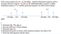
Transcribed Image Text:If the carrier signal is Vc (t) = Ve Sin (Wst). And the information signal is used to
generate AM wave Vm (t) = Vm Sin (t), the AM Bandwidth is equal to 12 KHz,
modulation index m = 0.5 and the spectrum frequency for AM is shown figure:
6
-100-6fm -100
-100+6fm
100-6fm 100 100+6fm
KHZ
|
1- determine Ws. Wm, fim. f.
2- draw the AM wave in time domain
3. determine Vm. Vc.
4-determine the power at carrier of the antenna resistance one ohm (1 2)
5- Write the AM equation with all values.
Expert Solution
This question has been solved!
Explore an expertly crafted, step-by-step solution for a thorough understanding of key concepts.
Step by stepSolved in 3 steps with 3 images

Knowledge Booster
Learn more about
Need a deep-dive on the concept behind this application? Look no further. Learn more about this topic, electrical-engineering and related others by exploring similar questions and additional content below.Similar questions
- = The design spectrum has Sps = 1.8, SD1 = 0.9, S₁ 1.1, I = 1.00, and R = 6. Determine C, if the period is 0.4 sec. Give the answer to three decimals. Assume that the period is not longer than TL.arrow_forwardA sequence of alternating 1s and 0s is transmitted as a square wave. What is the fundamentalfrequency and how many harmonics can be used if the available BW is 100 MHz and a data rate of 56Mbps is desired? Express the signal as a mathematical function of time (s(t)) and sketch the resultingsignal in both the time and frequency domains. Is this a “good enough” representation of the squarewave? Why or why not?arrow_forwardVolt/div = 37 V for red signal, Volt/div = 7 V for blue signal and Time/div = 11 s. What is the phase shift between these signals in terms of radians? (pi=3.14)arrow_forward
- 15. A 100-V carrier is modulated by a 1-kHz sine wave. Determine the sidefrequency amplitudes when m 0.75. (37.5 V) 16. A 1-MHz, 40-V peak carrier is modulated by a 5-kHz intelligence signal so that 0.7. This AM signal is fed to a 50- antenna. Calculate the power of each spectral component fed to the antenna. ( W, W) 17. Calculate the carrier and sideband power if the total transmitted power is 500 W in Problem 15. (390 W, 110 W) 18. The ac rms antenna current of an AM transmitter is 6.2 A when unmodulated and rises to 6.7 A when modulated. Calculate %m. (57.9%) 21. An AM transmitter has a 1-kW carrier and is modulated by three different sine waves having equal amplitudes. If , calculate the individual values of m and the total transmitted power. (0.462, 1.32 kW)arrow_forwardFind the wavelengths of (a) a 450 MHz, (b) a 650 MHz, (c) an 8 MHz, and (d) a 850 KHz signal.?arrow_forward.arrow_forward
- I need it asap A 2 kHz audio signal modulates a 50 MHz carrier, causing a frequency deviation of 2.5 kHz. Determine the bandwidth of the FM signal.arrow_forwardJI - 1 lal ahi X Meet - wwi-swim-sWZ DQLSchQF608hEnQEkoXPxD96ltxqUdhM3leAVMtKKDCKdBTVZSxw/formResponse Part 3: Short Problems bla 4 What is the instantaneous frequency (in Hertz) of the following radar FM signal at t = 1sec. ? x(t) = 12cos(20nt + nt?) 10 Hz 10.5 Hz None of the mentioned answers. 20 Hz 11 Hz 20.5 Hz 12 Hz O 21 Hz 國arrow_forwardAn FM signal has a deviation of 3 kHz and a modulating frequency of 1 kHz. Its total power is 5 W, developed across a 50 2 resistive load. The carrier fre- quency is 160 MHz. (a) Calculate the RMS signal voltage. (b) Calculate the RMS voltage at the carrier frequency and each of the first three sets of sidebands. (c) Calculate the frequency of each sideband for the first three sideband pairs. es Falerna avlop (d) Calculate the power at the carrier frequency, and in each sideband, for the first three pairs.arrow_forward
- I hope to write a simple summary so that I can save it because I have exams Difference between Hertz Antennas (half-wave) and Marconi (quarter-wave) Antennas.arrow_forwardIf the carrier signal is Vs (t) = Ve Sin (Wst). And the information signal is used to generate AM wave Vm (t) = Vm Sin (t), the AM Bandwidth is equal to 12 KHz, modulation index m = 0.5 and the spectrum frequency for AM is shown figure: 6 -100-6fm -100 -100+6fm 100-6fm 100 100+6fm KHZ | 1- determine Wc. Wm, fm. fe 2- draw the AM wave in time domain 3. determine Vm. Vcarrow_forward
arrow_back_ios
arrow_forward_ios
Recommended textbooks for you
 Introductory Circuit Analysis (13th Edition)Electrical EngineeringISBN:9780133923605Author:Robert L. BoylestadPublisher:PEARSON
 Delmar's Standard Textbook Of ElectricityElectrical EngineeringISBN:9781337900348Author:Stephen L. HermanPublisher:Cengage Learning
 Programmable Logic ControllersElectrical EngineeringISBN:9780073373843Author:Frank D. PetruzellaPublisher:McGraw-Hill Education
 Fundamentals of Electric CircuitsElectrical EngineeringISBN:9780078028229Author:Charles K Alexander, Matthew SadikuPublisher:McGraw-Hill Education
 Electric Circuits. (11th Edition)Electrical EngineeringISBN:9780134746968Author:James W. Nilsson, Susan RiedelPublisher:PEARSON
 Engineering ElectromagneticsElectrical EngineeringISBN:9780078028151Author:Hayt, William H. (william Hart), Jr, BUCK, John A.Publisher:Mcgraw-hill Education,

Introductory Circuit Analysis (13th Edition)
Electrical Engineering
ISBN:9780133923605
Author:Robert L. Boylestad
Publisher:PEARSON

Delmar's Standard Textbook Of Electricity
Electrical Engineering
ISBN:9781337900348
Author:Stephen L. Herman
Publisher:Cengage Learning

Programmable Logic Controllers
Electrical Engineering
ISBN:9780073373843
Author:Frank D. Petruzella
Publisher:McGraw-Hill Education

Fundamentals of Electric Circuits
Electrical Engineering
ISBN:9780078028229
Author:Charles K Alexander, Matthew Sadiku
Publisher:McGraw-Hill Education

Electric Circuits. (11th Edition)
Electrical Engineering
ISBN:9780134746968
Author:James W. Nilsson, Susan Riedel
Publisher:PEARSON

Engineering Electromagnetics
Electrical Engineering
ISBN:9780078028151
Author:Hayt, William H. (william Hart), Jr, BUCK, John A.
Publisher:Mcgraw-hill Education,