
Introductory Circuit Analysis (13th Edition)
13th Edition
ISBN: 9780133923605
Author: Robert L. Boylestad
Publisher: PEARSON
expand_more
expand_more
format_list_bulleted
Related questions
Question
thumb_up100%
1.) What is the current in the above circuit with a frequency of 330 Hz.
2.) What is the harmonic/resonant frequency of the above circuit?
Please show all work
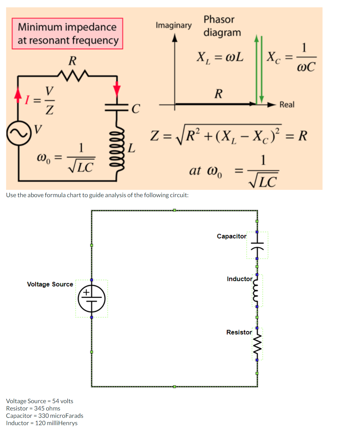

Transcribed Image Text:Minimum impedance
at resonant frequency
V
DIN
V
Z
Wo
R
√LC
Voltage Source
Voltage Source = 54 volts
Resistor = 345 ohms
④
с
Use the above formula chart to guide analysis of the following circuit:
Capacitor = 330 microfarads
Inductor = 120 milliHenrys
L
Imaginary
Phasor
diagram
X₁ = @L
R
at Wo =
Capacitor
Z= |R² + (X₁ − Xc)² = R
1
√LC
T
Inductor
Xc
Resistor
=
Real
1
@C
Expert Solution
This question has been solved!
Explore an expertly crafted, step-by-step solution for a thorough understanding of key concepts.

This is a popular solution

Trending nowThis is a popular solution!

Step by stepSolved in 3 steps with 3 images

Knowledge Booster


Learn more about
Need a deep-dive on the concept behind this application? Look no further. Learn more about this topic, electrical-engineering and related others by exploring similar questions and additional content below.Similar questions
- Refer to the parallel resonant circuit of Figure 21-41. 2 μΑΖ0 220 pF L V R fp = 800 kHz BW = 25 kHz FIGURE 21-41 Suppose the circuit has a resonant frequency of 800 kHz and a bandwidth of 25 kHz. a. Determine the value of the inductor, L, in henries. b. Calculate the value of the resistance, R, in ohms. c. Find V, IL, and power, P, at resonance. d. Find the approximate values of the half-power frequencies, fi and f2. e. Determine the voltage across the circuit at the lower half-power frequency, fi, and show that the power dissipated by the resistor at this frequency is half the power dissipated at the resonant frequency. a. L = 180 µH b. R, = 28.9 kſN c. V = 57.9 mV Z0° Iz = 64.0 µAZ-90° P= 115 nW d. fi = 788 kHz f2 = 813 kHz e. V = 41.1 mVZ44.72° P = 58 nW © Cengage Leaming 2013arrow_forwardH: A 4V peak sine wave is fed to the circuit and a 1V peak sine wave results. Determine the gain in units of db. Va R1 ww Vb T C1 Gain Frequencyarrow_forwardA Parallel Resonant ckt is given in the figure. Calculate Wo, W1, W2 , QF & Bw.arrow_forward
- Skin effect becomes less effective in Lower frequency Higher frequency Both higher and lower frequencies none of the choicesarrow_forwardQuestion No. 4 M₁ = 1 le lo 17. A series R – L – C circuit has R = 50 N, L = 100 µH and C = 1 µF. the lower half power frequency of the circuit isarrow_forwardIn a series R-L-C circuit, the resistor has a reactance of 2 ohms, the capacitor has a capacitance of 0.5 F, and the inductance of the inductor is 9 H. What is the frequency of alternating current to achieve a resonance state?arrow_forward
- The below 4 figures are the angle of the transfer function of passive filters. Phase (deg) -45- Phase (deg) (Cep) sid 45 10 10 Frequency (radisec) 10² Frequency (rad/sec) Figure-1 shows the frequency response of Figure-2 shows the frequency response of Figure-3 shows the frequency response of Figure-4 shows the frequency response of 4) ( + 4 10 10" 10arrow_forwardFor the given circuit in figure 6, determine the upper and lowerfrequencies of oscillation and also the Hartley oscillators bandwidth.arrow_forwardIf Vin is 3V, RF is 12k2, and Rg is 6k2, determine Vo. Answer should be in V. R6 m Iin Vin I feedback + RF m Vcc -VEE Voutarrow_forward
- What is the voltage ratio that corresponds to 88.57 dB? O a) 2404 O b) 26,833 Oc) 4/(5 × 105) O d) 24(3 x 10⁷)arrow_forwardIncreasing the resistance of a series resonant R-L-C circuit will do which of the following? a) decrease the resonant frequency. O b) increase the Q factor of the circuit. O c) increase the current flow in the circuit. d) decrease the current flow in the circuit.arrow_forward
arrow_back_ios
arrow_forward_ios
Recommended textbooks for you
- Introductory Circuit Analysis (13th Edition)Electrical EngineeringISBN:9780133923605Author:Robert L. BoylestadPublisher:PEARSON
 Delmar's Standard Textbook Of ElectricityElectrical EngineeringISBN:9781337900348Author:Stephen L. HermanPublisher:Cengage Learning
 Programmable Logic ControllersElectrical EngineeringISBN:9780073373843Author:Frank D. PetruzellaPublisher:McGraw-Hill Education
  Fundamentals of Electric CircuitsElectrical EngineeringISBN:9780078028229Author:Charles K Alexander, Matthew SadikuPublisher:McGraw-Hill Education
 Electric Circuits. (11th Edition)Electrical EngineeringISBN:9780134746968Author:James W. Nilsson, Susan RiedelPublisher:PEARSON
 Engineering ElectromagneticsElectrical EngineeringISBN:9780078028151Author:Hayt, William H. (william Hart), Jr, BUCK, John A.Publisher:Mcgraw-hill Education,
Introductory Circuit Analysis (13th Edition)
Electrical Engineering
ISBN:9780133923605
Author:Robert L. Boylestad
Publisher:PEARSON
Delmar's Standard Textbook Of Electricity
Electrical Engineering
ISBN:9781337900348
Author:Stephen L. Herman
Publisher:Cengage Learning
Programmable Logic Controllers
Electrical Engineering
ISBN:9780073373843
Author:Frank D. Petruzella
Publisher:McGraw-Hill Education
Fundamentals of Electric Circuits
Electrical Engineering
ISBN:9780078028229
Author:Charles K Alexander, Matthew Sadiku
Publisher:McGraw-Hill Education
Electric Circuits. (11th Edition)
Electrical Engineering
ISBN:9780134746968
Author:James W. Nilsson, Susan Riedel
Publisher:PEARSON
Engineering Electromagnetics
Electrical Engineering
ISBN:9780078028151
Author:Hayt, William H. (william Hart), Jr, BUCK, John A.
Publisher:Mcgraw-hill Education,