
Related questions
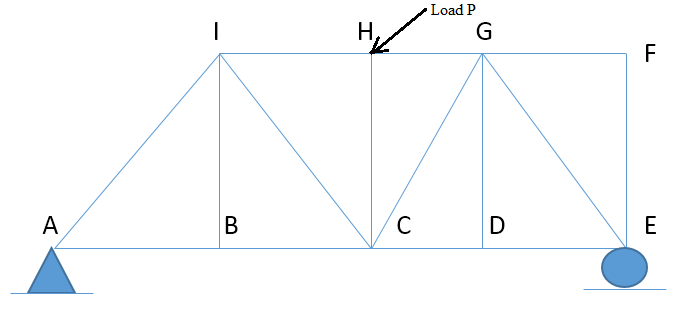
Zero-Force Members are structural members that support No loading but aid in the stability of the truss. Tips on getting the zero-force members: 1. there is no external load or reaction at that joint 2. Insufficient structural members to satisfy or "balance" the system: Summation of forces along the horizontal and vertical 3. two of the members are collinear As shown in the figure, structural members of zero-force members can be noticed through observation.
At a glance, it can be inferred that the member FG and FE are zero force members, because: First, there is no external load applied on the joint Secondly, taking the Joint F, if Summation of Forces along horizontal = 0 is executed, only the member FG has the horizontal component, or the "ability" to "balance" the system, and if Summation of Forces along vertical = 0 is executed, the member FE has the vertical component, or the "ability" to "balance" the system only. Aside from members FG and FE, through observation, determine the other zero-force members.


Step by stepSolved in 2 steps with 2 images


- The truss below is : a.Unstable internally and unstable externally b.Unstable internally and stable externally c.Stable internally and stable externally d.Stable internally and unstable externallyarrow_forwardDefine the elemental stiffness matrix for element 2-3 in the given truss structure 1 45 90 45 2 3arrow_forwardWhich one of the following statements is TRUE • In a beam-column, the bending moment will delay the buckling phenomenon • The location of neutral axis coincides with the centroid of a symmetrical beam-column section • In-plane capacity does not need to be checked for members under combined tension and bending • Euler buckling is an out-of-plane global buckling phenomenonarrow_forward
- The elements of a truss structure are modeled as O 1-force members O 4-force members. O2-force members O frames for the purposes of calculation.arrow_forwardThe truss ABC is constructed of three titanium (E Ti =17.4×10 3 ksi) members. A horizontal force of 1.8 kip and an unknown force P are applied to the truss at point B as shown. Member AB has a cross-sectional area of 0.1in 2 , member BC has a cross-sectional area of 0.0025ft 2 , and member AC has a cross-sectional area of 0.2 in2. b) Determine the magnitude of the force P that is required to displace the roller at point C to the right by .03 inches.arrow_forward
 Structural Analysis (10th Edition)Civil EngineeringISBN:9780134610672Author:Russell C. HibbelerPublisher:PEARSON
 Principles of Foundation Engineering (MindTap Cou...Civil EngineeringISBN:9781337705028Author:Braja M. Das, Nagaratnam SivakuganPublisher:Cengage Learning
 Fundamentals of Structural AnalysisCivil EngineeringISBN:9780073398006Author:Kenneth M. Leet Emeritus, Chia-Ming Uang, Joel LanningPublisher:McGraw-Hill Education
 Traffic and Highway EngineeringCivil EngineeringISBN:9781305156241Author:Garber, Nicholas J.Publisher:Cengage Learning