Structural Analysis
6th Edition
ISBN: 9781337630931
Author: KASSIMALI, Aslam.
Publisher: Cengage,
expand_more
expand_more
format_list_bulleted
Question
thumb_up100%

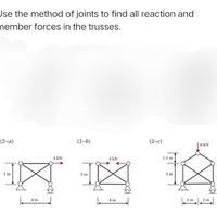
Transcribed Image Text:Jse the method of joints to find all reaction and
nember forces in the trusses.
(2-а)
(2-b)
(2-c)
| 6 kN
4 kN
4 kN
1.5 m
3 m
3 m
3 m
4 m
4 m
2 m
2 m
Expert Solution
This question has been solved!
Explore an expertly crafted, step-by-step solution for a thorough understanding of key concepts.
Step by stepSolved in 7 steps with 7 images

Knowledge Booster
Similar questions
- please help me, thanks in advance!arrow_forward2. Use the method of joints to determine the internal forces in each member of the truss. The structure is supported by a roller at A and a pin at C. 400 N -3 m B -3 m- 600 N 4 marrow_forward1. Use the method of sections to determine the internal forces in members BC, GC, and GF. The structure is supported by a pin at D and a roller at E. A -2 m- 1000 N B G a a -2 m- C F -2 m- E 2 marrow_forward
- Determine the forces acting in members FE, EB and BC of the truss use the method of sections. The truss is supported by a pin at A and a roller at D. - 2 m- 1.5 m E -2 m - 2 m B 11 kN 22 kNarrow_forwardThe truss ABCDEF is pinned at A and F. What is the force in bar BE when the external force P= 167 kN? 3m 3m K * K B 9m P D E 6m 6marrow_forwardGiven the Truss as shown below with load P and dimension L. Using Method of Joints, determine the following: a.) The External Reaction at Point A in terms of P. b.) The External Reaction at Point E in terms of P. c.) The Force at Member BF in terms of P. L/2 В D F H L/2 A P P E - L- L - L L -arrow_forward
- Link-2, shown in the figure, is 30 mm wide, has 12 mm diameter bearings atthe ends, and is cut from low carbon steel bar having a minimum yield strength of190 MPa. The end-condition constants for link-2 are C = 1 and C = 1.2 for bucklingin and out of the drawing, respectively.a) Draw necessary and clear free-body diagrams to determine the reactions atthe supports and the load on both member-2 and member-3. b) Determine a suitable thickness for link-2, based on a design factor of safetyηD = 4, and considering a material having E = 207 GPa, and a minimum yieldstrength Sy = 350 MPa. c) Determine the stress and resulting factor of safety for each pin, and state yoursuggestions in case of design factors less than 4. Use appropriate (SI) units as it applies (if any.)arrow_forwardDetermine the force in members DE and DF of the truss shown when P= 25 kips. F D H 7.5 ft В A L C E G I K P P P 6 panels @ 6 ft = 36 ft |kips. [(Click to select) | kips. (Click to select) The force in DE is The force in DF isarrow_forward2. Use the method of sections to determine the internal forces in members JI, DI, and DE. The structure is supported by a pin at A and a roller at G. L J 3 m K AN B H E F C D 2 -2 m--2 m2 m2 m2 m--2 m- 20 KN 30 kN 40 kN Garrow_forward
arrow_back_ios
SEE MORE QUESTIONS
arrow_forward_ios
Recommended textbooks for you

 Structural Analysis (10th Edition)Civil EngineeringISBN:9780134610672Author:Russell C. HibbelerPublisher:PEARSON
 Principles of Foundation Engineering (MindTap Cou...Civil EngineeringISBN:9781337705028Author:Braja M. Das, Nagaratnam SivakuganPublisher:Cengage Learning
 Fundamentals of Structural AnalysisCivil EngineeringISBN:9780073398006Author:Kenneth M. Leet Emeritus, Chia-Ming Uang, Joel LanningPublisher:McGraw-Hill Education
 Traffic and Highway EngineeringCivil EngineeringISBN:9781305156241Author:Garber, Nicholas J.Publisher:Cengage Learning


Structural Analysis (10th Edition)
Civil Engineering
ISBN:9780134610672
Author:Russell C. Hibbeler
Publisher:PEARSON

Principles of Foundation Engineering (MindTap Cou...
Civil Engineering
ISBN:9781337705028
Author:Braja M. Das, Nagaratnam Sivakugan
Publisher:Cengage Learning

Fundamentals of Structural Analysis
Civil Engineering
ISBN:9780073398006
Author:Kenneth M. Leet Emeritus, Chia-Ming Uang, Joel Lanning
Publisher:McGraw-Hill Education


Traffic and Highway Engineering
Civil Engineering
ISBN:9781305156241
Author:Garber, Nicholas J.
Publisher:Cengage Learning