
Introductory Circuit Analysis (13th Edition)
13th Edition
ISBN: 9780133923605
Author: Robert L. Boylestad
Publisher: PEARSON
expand_more
expand_more
format_list_bulleted
Related questions
Question
Complete the following timing diagrams for Q and Q¯ for each FF type. Assume they are triggered on the positive rising edge of the clock (C).
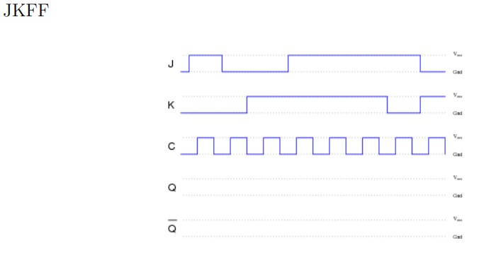

Transcribed Image Text:**JK Flip-Flop (JKFF) Timing Diagram Explanation**
The image shows a timing diagram for a JK flip-flop (JKFF), a type of digital memory circuit used in various electronic applications. The diagram consists of five waveforms labeled J, K, C, Q, and the complemented Q (often denoted as Q̅). Each waveform illustrates the behavior of the JK flip-flop over time.
1. **J Input (J):** This waveform represents the "J" input of the JK flip-flop. It has several high (logic 1) and low (logic 0) transitions. The state of the J input influences how the flip-flop changes states.
2. **K Input (K):** This waveform represents the "K" input of the JK flip-flop. Similar to the J input, it has high and low states. The K input, together with the J input, determines the behavior of the flip-flop.
3. **Clock (C):** This is the clock input waveform. It consists of a series of regular pulses and is crucial for synchronizing the changes in the output states of the flip-flop. On each positive or negative edge of the clock pulse, the flip-flop evaluates the J and K inputs to determine the next state.
4. **Q Output (Q):** This waveform shows the Q output of the flip-flop. Depending on the J and K inputs and the clock's trigger, Q changes its state. Q represents the flip-flop's main output.
5. **Complemented Q Output (Q̅):** This is the complemented or inverted Q output waveform, also known as Q-bar. It is simply the inverse of the Q output.
**Behavior Summary:**
- When J = 1 and K = 0, the Q output is set (Q = 1).
- When J = 0 and K = 1, the Q output is reset (Q = 0).
- When J = 1 and K = 1, the Q output is toggled (changes state).
- When J = 0 and K = 0, the Q output remains unchanged.
**Usage:**
JK flip-flops are essential components in digital circuits, often used for counters, shift registers, and various memory applications to maintain a stable state defined by control signals.
Expert Solution
arrow_forward
Step 1
Timing diagrams for Q and Q' for each flip-flop type

Step by stepSolved in 2 steps with 1 images

Knowledge Booster


Learn more about
Need a deep-dive on the concept behind this application? Look no further. Learn more about this topic, electrical-engineering and related others by exploring similar questions and additional content below.Similar questions
- Draw the 555 timer circuit that produces a square wave signal with Thigh=2ms and Tlow=1ms by calculating the resistor and capacitor values.arrow_forward11. Determine the condition of the SCR in the following conditions: activated or not-activated. Vcc-500V Vcc=10V Vcc=10V Q Vcc=100V 10 ka 1 ka 1 ko Ig=1µA 1 kQ (a) (b) (c) (d)arrow_forwardClock CLR' K PRE'arrow_forward
Recommended textbooks for you
- Introductory Circuit Analysis (13th Edition)Electrical EngineeringISBN:9780133923605Author:Robert L. BoylestadPublisher:PEARSON
 Delmar's Standard Textbook Of ElectricityElectrical EngineeringISBN:9781337900348Author:Stephen L. HermanPublisher:Cengage Learning
 Programmable Logic ControllersElectrical EngineeringISBN:9780073373843Author:Frank D. PetruzellaPublisher:McGraw-Hill Education
  Fundamentals of Electric CircuitsElectrical EngineeringISBN:9780078028229Author:Charles K Alexander, Matthew SadikuPublisher:McGraw-Hill Education
 Electric Circuits. (11th Edition)Electrical EngineeringISBN:9780134746968Author:James W. Nilsson, Susan RiedelPublisher:PEARSON
 Engineering ElectromagneticsElectrical EngineeringISBN:9780078028151Author:Hayt, William H. (william Hart), Jr, BUCK, John A.Publisher:Mcgraw-hill Education,
Introductory Circuit Analysis (13th Edition)
Electrical Engineering
ISBN:9780133923605
Author:Robert L. Boylestad
Publisher:PEARSON
Delmar's Standard Textbook Of Electricity
Electrical Engineering
ISBN:9781337900348
Author:Stephen L. Herman
Publisher:Cengage Learning
Programmable Logic Controllers
Electrical Engineering
ISBN:9780073373843
Author:Frank D. Petruzella
Publisher:McGraw-Hill Education
Fundamentals of Electric Circuits
Electrical Engineering
ISBN:9780078028229
Author:Charles K Alexander, Matthew Sadiku
Publisher:McGraw-Hill Education
Electric Circuits. (11th Edition)
Electrical Engineering
ISBN:9780134746968
Author:James W. Nilsson, Susan Riedel
Publisher:PEARSON
Engineering Electromagnetics
Electrical Engineering
ISBN:9780078028151
Author:Hayt, William H. (william Hart), Jr, BUCK, John A.
Publisher:Mcgraw-hill Education,