
Introductory Circuit Analysis (13th Edition)
13th Edition
ISBN: 9780133923605
Author: Robert L. Boylestad
Publisher: PEARSON
expand_more
expand_more
format_list_bulleted
Related questions
Question
Give the basic current mirror below. What would the value of W/L of M2 in order for to have an output twice its Iref (current reference)?
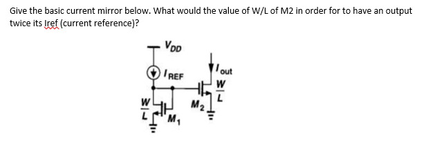

Transcribed Image Text:Give the basic current mirror below. What would the value of W/L of M2 in order for to have an output
twice its Iref (current reference)?
VDD
IREF
M₂
out
W
Expert Solution
This question has been solved!
Explore an expertly crafted, step-by-step solution for a thorough understanding of key concepts.

Step by stepSolved in 4 steps with 4 images

Knowledge Booster


Learn more about
Need a deep-dive on the concept behind this application? Look no further. Learn more about this topic, electrical-engineering and related others by exploring similar questions and additional content below.Similar questions
- A. Detemine the value of the collector resistor in an npn transistor amplifier with Ppc = 250, VBB = 2.5 V, Vcc = 9 V, VCE = 4 V, and Rg = 100 k2. B. Detemine Icsat) for the transistor in below Figure. What is the value of IB necessary to produce saturation? What minimum value of VIN is necessary for saturation? Assume %3D VCE(sat) = 0 V. +5 V 10 kN Rg VINO BDc = 150 1.0 MNarrow_forwardUsing the 2N6504 SCR in constructing the basic SCR circuit in figure, with gate triggering current, IGT = 9.0mA and voltage, VGT 1V. What is the input voltage that turns the SCR on using 1k gate resistor?arrow_forward2. 3. 5. Using the data when the gate voltage is 0, explain how you could use your JFET as a two-terminal current source that gives a current of Ipss. (a) Does the experimental data indicate that the transconductance is a constant at all points? (b) From your experimental data, what evidence indicates that a JFET is a nonlinear device? Why should a JFET be operated with only reverse bias on the gate source?arrow_forward
- 5. For the following circuit with ideal OPAM and positive saturation voltage Vsat+ = 9V and negative saturation voltage Vsat-=-8V. Find: a. It is a function of V1, in active region and positive and negative saturation regions. b. The current iA in active region and in positive and negative saturation regions. Remember that no current enters the inverting and non-inverting terminals, and also V+ is different from V- when the OPAM is saturated. 10ΚΩ w 1ΚΩ www Va we+ 1A 1ΚΩ 1ΚΩ w 10kQarrow_forwardIn which region BJT is working?arrow_forwardQI Ref RG RM A1 Vou VOUT Digital A DACI Input, DIN VDAC Figure QI Figure QI shows the circuit used to condition the output of the n- bit Digital to Analog Converter "DACI" having a digital input value of Dw. DACI may be assumed to have a voltage output with zero source resistance coded in "straight binary" such that • For a binary input of Dy = 000...000 the output voltage vaac is 0 V • For a binary input of Dw = 111..111 the output voltage vaac is Vn Where Vg is a positive voltage reference. Neglecting Ry and assuming that opamp Al is ideal, show that the output voltage v, is (а) OUT R. for D, - 000000 R (i) Vay- ref (ii) Vor for D,-111..111 Hence choose values of Ro and R to give an output voltage range -V Svar S (iii) Re-draw Figure Q1 to show all sources of DC opamp error and say why they have the signs you have given them. (b) Hence derive an expression for the emor in vug due to opamp DC input cur. and voltage errors including both bias and offset currents. (c) If the two…arrow_forward
- 9. A 6-bit DAC has an input of 1001012 and uses a 10.0 V reference. i. Find the output voltage produced. ii. Specify the conversion resolutionsarrow_forwardDetermine the input resistance Rin as indicated in the figure. Ignore resistor ro of the transistor and capacitors are large. A. Rin = R1//R2//R3 B. Rin = R2//R3 (//R4//R5) C. Rin = R2//R3 // ( r π + [1+gm r π ] (//R4//R5) ) D. Rin = R2//R3 // r π (//R4//R5) )arrow_forward
arrow_back_ios
arrow_forward_ios
Recommended textbooks for you
- Introductory Circuit Analysis (13th Edition)Electrical EngineeringISBN:9780133923605Author:Robert L. BoylestadPublisher:PEARSON
 Delmar's Standard Textbook Of ElectricityElectrical EngineeringISBN:9781337900348Author:Stephen L. HermanPublisher:Cengage Learning
 Programmable Logic ControllersElectrical EngineeringISBN:9780073373843Author:Frank D. PetruzellaPublisher:McGraw-Hill Education
  Fundamentals of Electric CircuitsElectrical EngineeringISBN:9780078028229Author:Charles K Alexander, Matthew SadikuPublisher:McGraw-Hill Education
 Electric Circuits. (11th Edition)Electrical EngineeringISBN:9780134746968Author:James W. Nilsson, Susan RiedelPublisher:PEARSON
 Engineering ElectromagneticsElectrical EngineeringISBN:9780078028151Author:Hayt, William H. (william Hart), Jr, BUCK, John A.Publisher:Mcgraw-hill Education,
Introductory Circuit Analysis (13th Edition)
Electrical Engineering
ISBN:9780133923605
Author:Robert L. Boylestad
Publisher:PEARSON
Delmar's Standard Textbook Of Electricity
Electrical Engineering
ISBN:9781337900348
Author:Stephen L. Herman
Publisher:Cengage Learning
Programmable Logic Controllers
Electrical Engineering
ISBN:9780073373843
Author:Frank D. Petruzella
Publisher:McGraw-Hill Education
Fundamentals of Electric Circuits
Electrical Engineering
ISBN:9780078028229
Author:Charles K Alexander, Matthew Sadiku
Publisher:McGraw-Hill Education
Electric Circuits. (11th Edition)
Electrical Engineering
ISBN:9780134746968
Author:James W. Nilsson, Susan Riedel
Publisher:PEARSON
Engineering Electromagnetics
Electrical Engineering
ISBN:9780078028151
Author:Hayt, William H. (william Hart), Jr, BUCK, John A.
Publisher:Mcgraw-hill Education,