Introductory Circuit Analysis (13th Edition)
13th Edition
ISBN: 9780133923605
Author: Robert L. Boylestad
Publisher: PEARSON
expand_more
expand_more
format_list_bulleted
Question
thumb_up100%
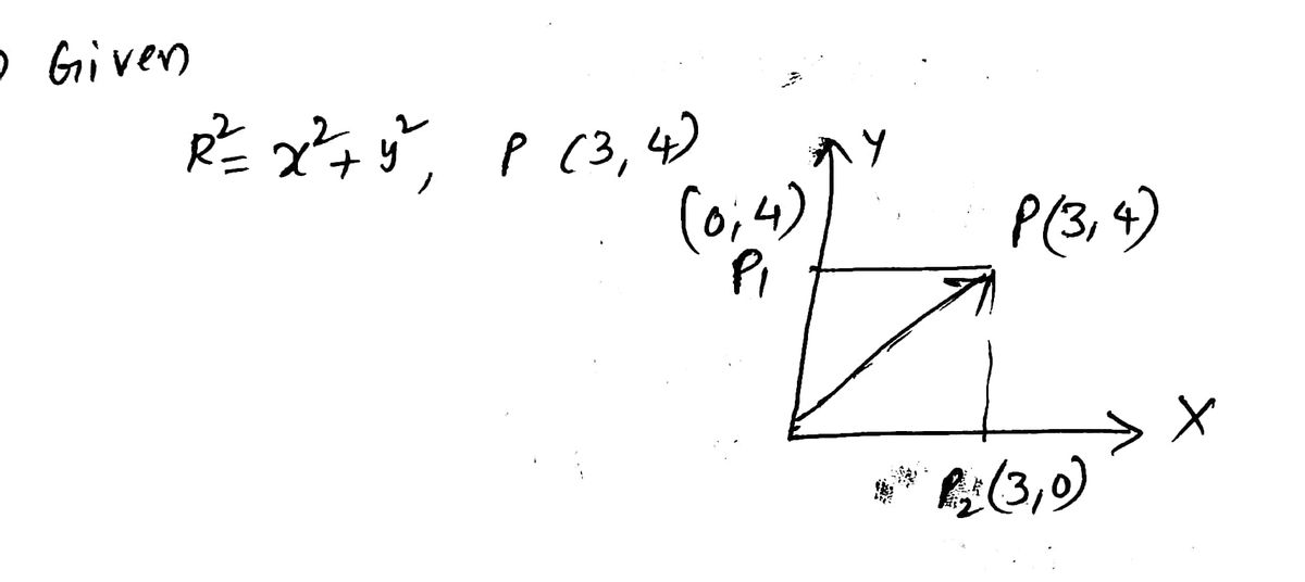
U can use the second picture to derive part b and c I know how to do part a can u explain clearly how to do part b and c I am lost on the parameter of the integration and how to setup the integration operation ?
![**Example A (continued 3/4)**
(b) along the path \( OP_1P \)
\[ C = OP_1P = OP_1 + P_1P \]
\[
d\vec{\ell} = d\vec{y}; \quad [OP_1]
\]
\[
d\vec{\ell} = d\vec{x}; \quad [P_1P]
\]
\[
\int_C r^2 \, d\vec{\ell} = \int_0^{P_1} r^2 \, d\vec{y} + \int_{P_1}^P r^2 \, d\vec{x}
\]
\[
= \hat{a_y} \int_0^1 (0 + y^2) \, dy + \hat{a_x} \int_0^1 (x^2 + 1) \, dx
\]
\[
= \hat{a_y} (1/3) + \hat{a_x} (4/3)
\]
**Diagram Explanation:**
The diagram is a graph with points labeled on a coordinate plane. The path being evaluated is highlighted as follows:
- Point \( O \) is at the origin \((0,0)\).
- Point \( P_1 \) is at \( (0, 1) \).
- Point \( P_2 \) is at \( (1, 0) \).
- Point \( P \) is at \( (1, 1) \).
The path \( OP_1P \) is shown with lines indicating movement first along the \( y \)-axis from \( O \) to \( P_1 \), and then along the \( x \)-axis from \( P_1 \) to \( P \). The calculations are shown for integrating along these paths separately.](https://content.bartleby.com/qna-images/question/6e3992ca-2280-40ba-b65a-68dc98c03d5d/bf66b3be-c7d4-4d5e-a513-8ae1842e7dfd/y5b8g4c_thumbnail.jpeg)
Transcribed Image Text:**Example A (continued 3/4)**
(b) along the path \( OP_1P \)
\[ C = OP_1P = OP_1 + P_1P \]
\[
d\vec{\ell} = d\vec{y}; \quad [OP_1]
\]
\[
d\vec{\ell} = d\vec{x}; \quad [P_1P]
\]
\[
\int_C r^2 \, d\vec{\ell} = \int_0^{P_1} r^2 \, d\vec{y} + \int_{P_1}^P r^2 \, d\vec{x}
\]
\[
= \hat{a_y} \int_0^1 (0 + y^2) \, dy + \hat{a_x} \int_0^1 (x^2 + 1) \, dx
\]
\[
= \hat{a_y} (1/3) + \hat{a_x} (4/3)
\]
**Diagram Explanation:**
The diagram is a graph with points labeled on a coordinate plane. The path being evaluated is highlighted as follows:
- Point \( O \) is at the origin \((0,0)\).
- Point \( P_1 \) is at \( (0, 1) \).
- Point \( P_2 \) is at \( (1, 0) \).
- Point \( P \) is at \( (1, 1) \).
The path \( OP_1P \) is shown with lines indicating movement first along the \( y \)-axis from \( O \) to \( P_1 \), and then along the \( x \)-axis from \( P_1 \) to \( P \). The calculations are shown for integrating along these paths separately.

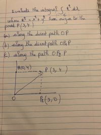
Transcribed Image Text:**Title: Evaluating the Integral of \( R^2 \) Along Different Paths**
**Objective:**
Evaluate the integral \(\int R^2 \, dl\) where \(R^2 = x^2 + y^2\), from the origin \(O\) to the point \(P(3,4)\).
**Paths for Evaluation:**
1. **Path (a):** Along the direct path \(OP\)
2. **Path (b):** Along the direct path \(OAP\)
3. **Path (c):** Along the path \(OP_2P\)
**Diagram Explanation:**
- **Coordinates:**
- Origin \(O(0,0)\)
- Point \(A(0,4)\)
- Point \(P_2(3,0)\)
- Point \(P(3,4)\)
The diagram illustrates three paths:
- **Path \(OP\):** A diagonal line directly from \(O\) to \(P(3,4)\).
- **Path \(OAP\):** A two-segment path, first going vertically to \(A(0,4)\) and then horizontally to \(P(3,4)\).
- **Path \(OP_2P\):** A two-segment path, first going horizontally to \(P_2(3,0)\) and then vertically to \(P(3,4)\).
**Approach:**
This exercise requires evaluating an integral along different paths between defined points, exploring how the integral of \(R^2\) varies based on the path taken. This helps illustrate properties such as path independence in vector fields when applicable.
Expert Solution
arrow_forward
Step 1

Step by stepSolved in 3 steps with 3 images

Knowledge Booster
Similar questions
- Listen A 12 bit DAC has a lower reference voltage of OV and an upper reference voltage of 3.0V What is the output voltage for a code of Ox74B? Round the answer to 2 decimal places. a) 1.37V Ob) 1.50V c) 1.60V O d) 1.12Varrow_forwardQ. A straight binary sequence is applied to a 4-bit DAC, and the output in figure below is observed. What is the problem? Output 15 14 13 12 11 10 9 8 7 6 5 4 3 2 1 0000 1000 0100 0011 0100 0101- 0110 1110 0001 1001- 1010 1101 0011 1101 0111 Binary input Electrical Engineering Department/ University of Basraharrow_forwardWhat is the output (in decimal format) of a 10-bit unipolar A/D converter for the input of 100mV? Assume that the converter uses 5V as a reference voltage for conversion purposes. The converter input range is 0V to 5V. Round your answer to the nearest integer value.arrow_forward
- Can you help me with this question? Thank you!arrow_forwardOUTPUT ( NEED NEAT HANDWRITTEN SOLUTION ONLY OTHERWISE DOWNVOTE).arrow_forward2) approximately draw Vout for the circuits below, separately. Point out which one is a rectifier which one is a clipping circuit. Use Vp = 0.7V. Input signal 2tVin 1.5 1 0.5 -0.5 -1 -1.5 -2 Circuit (a) Circuit (b) Vin Vout Vin Vaut R 2 Vonut 1.5 1.5 1 1 0.5 0.5 1 3 4 7 1 2 3 6 7 -0.5 -0.5 -1 -1 -1.5 -1.5 -2, -2arrow_forward
- cuicuit designed in winknown isubuenit, va resistance R = 2.8K2 and two identical silicon BITS T1 and 12 with 72 and T2 with forward gains BF = 200. The supply voltage Vcc =-25 volts Vcc=25 volts Sub-circuit JICA T2 IB₁1 IB12 VIR R = 28K2 VIC, 2 GIND IB, 1 and Ic, s designate the base and collector current of T2 vespectively where as the courrents IB,₁2 and IG2 designate the base and the collector currents of T2 respectively. T2 and 12 operate in forward active mode Assume that IB, 1 and IB₁2 are equal · VBE, on = 0.8 molt (Threshold woltage) (a) What is the value of the current IR through vesistance R.? (MA) (b) what is the value of the base vaurrent IB, 1? (MA) (c) what is the value of the collector Ic₁₁? (MA) (d) The evicuit idesigned using Resistance Rand Transistors T₁ and To performs an electronic function to connect to sub circut which function is it?arrow_forwardQ. A straight binary sequence is applied to a 4-bit DAC, and the output in figure below is observed. What is the problem? Output 15 14 13 12 11 10 9 8 7 6 5 4 3 2 1 0000 1000 0010 0011 0010 -1010 0110 1110 0001 1001- -otor 1011 H0011 1101- 0111 1111 Binary input Electrical Engineering Department/ University of Bauraarrow_forwardI need the answer as soon as possiblearrow_forward
- Design a 4-bit 4x1 multiplexer using four 4x1 multiplexers please do not write other examples on the internet remember that the correct answer should have 1 output and only 4 inputs!arrow_forwardQ44) In the STM diagram fragment below, we see five transitions marked with italic letters. Which option cannot have a guard condition added? dev2/x=x+1 A. a B. b C. c D. d E. e b a/beh Ev1/beh с earrow_forward
arrow_back_ios
arrow_forward_ios
Recommended textbooks for you
 Introductory Circuit Analysis (13th Edition)Electrical EngineeringISBN:9780133923605Author:Robert L. BoylestadPublisher:PEARSON
 Delmar's Standard Textbook Of ElectricityElectrical EngineeringISBN:9781337900348Author:Stephen L. HermanPublisher:Cengage Learning
 Programmable Logic ControllersElectrical EngineeringISBN:9780073373843Author:Frank D. PetruzellaPublisher:McGraw-Hill Education
 Fundamentals of Electric CircuitsElectrical EngineeringISBN:9780078028229Author:Charles K Alexander, Matthew SadikuPublisher:McGraw-Hill Education
 Electric Circuits. (11th Edition)Electrical EngineeringISBN:9780134746968Author:James W. Nilsson, Susan RiedelPublisher:PEARSON
 Engineering ElectromagneticsElectrical EngineeringISBN:9780078028151Author:Hayt, William H. (william Hart), Jr, BUCK, John A.Publisher:Mcgraw-hill Education,

Introductory Circuit Analysis (13th Edition)
Electrical Engineering
ISBN:9780133923605
Author:Robert L. Boylestad
Publisher:PEARSON

Delmar's Standard Textbook Of Electricity
Electrical Engineering
ISBN:9781337900348
Author:Stephen L. Herman
Publisher:Cengage Learning

Programmable Logic Controllers
Electrical Engineering
ISBN:9780073373843
Author:Frank D. Petruzella
Publisher:McGraw-Hill Education

Fundamentals of Electric Circuits
Electrical Engineering
ISBN:9780078028229
Author:Charles K Alexander, Matthew Sadiku
Publisher:McGraw-Hill Education

Electric Circuits. (11th Edition)
Electrical Engineering
ISBN:9780134746968
Author:James W. Nilsson, Susan Riedel
Publisher:PEARSON

Engineering Electromagnetics
Electrical Engineering
ISBN:9780078028151
Author:Hayt, William H. (william Hart), Jr, BUCK, John A.
Publisher:Mcgraw-hill Education,