Introductory Circuit Analysis (13th Edition)
13th Edition
ISBN: 9780133923605
Author: Robert L. Boylestad
Publisher: PEARSON
expand_more
expand_more
format_list_bulleted
Question
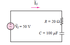
Calculate the apparent power, real power, and
reactive power for the circuit shown in Figure.
Draw the power triangle. Assume f = 60 Hz.

Transcribed Image Text:Is
R = 20 23
Vs = 50 V
С 3D100 иF
Expert Solution
This question has been solved!
Explore an expertly crafted, step-by-step solution for a thorough understanding of key concepts.
Step by stepSolved in 8 steps with 9 images

Knowledge Booster
Learn more about
Need a deep-dive on the concept behind this application? Look no further. Learn more about this topic, electrical-engineering and related others by exploring similar questions and additional content below.Similar questions
- Design a circuit to limit a 20 V rms sinusoidal voltage to a maximum positive amplitude of 10 V and a maximum negative amplitude of -5 Vusing a single 14 V dc voltage sourcearrow_forwardThe peak amplitude of the sinusoidal voltage source in the circuit shown in (Figure 1) is 150√2 V and its period is 200 μs. The load resistor can be varied from 0 to 20 2 and the load inductor can be varied from 1 to 8 mH Part A Calculate the average power delivered to the load when R = 10 and Lo = 6 mH Express your answer to three significant figures and include the appropriate units. P = 9.00 W Figure 300 Ω w 1μF Ro 1 of 1 Submit Previous Answers Correct Determine the settings of R, and Lo that will result in the most average power being transferred to Ro Part B Find Ro Express your answer to three significant figures and include the appropriate units. НА ? Ro= Value Units Submit Request Answer Part C Find Lo Express your answer to three significant figures and include the appropriate units. HA ? Lo= Value Units Submit Request Answerarrow_forwardAn inductor and a 470 ohm resistor are connected in series with a function generator. The current is 53.7mA RMS 8kHz. The reactive power is 2.32 var. Find the value of the inductance.arrow_forward
Recommended textbooks for you
 Introductory Circuit Analysis (13th Edition)Electrical EngineeringISBN:9780133923605Author:Robert L. BoylestadPublisher:PEARSON
 Delmar's Standard Textbook Of ElectricityElectrical EngineeringISBN:9781337900348Author:Stephen L. HermanPublisher:Cengage Learning
 Programmable Logic ControllersElectrical EngineeringISBN:9780073373843Author:Frank D. PetruzellaPublisher:McGraw-Hill Education
 Fundamentals of Electric CircuitsElectrical EngineeringISBN:9780078028229Author:Charles K Alexander, Matthew SadikuPublisher:McGraw-Hill Education
 Electric Circuits. (11th Edition)Electrical EngineeringISBN:9780134746968Author:James W. Nilsson, Susan RiedelPublisher:PEARSON
 Engineering ElectromagneticsElectrical EngineeringISBN:9780078028151Author:Hayt, William H. (william Hart), Jr, BUCK, John A.Publisher:Mcgraw-hill Education,

Introductory Circuit Analysis (13th Edition)
Electrical Engineering
ISBN:9780133923605
Author:Robert L. Boylestad
Publisher:PEARSON

Delmar's Standard Textbook Of Electricity
Electrical Engineering
ISBN:9781337900348
Author:Stephen L. Herman
Publisher:Cengage Learning

Programmable Logic Controllers
Electrical Engineering
ISBN:9780073373843
Author:Frank D. Petruzella
Publisher:McGraw-Hill Education

Fundamentals of Electric Circuits
Electrical Engineering
ISBN:9780078028229
Author:Charles K Alexander, Matthew Sadiku
Publisher:McGraw-Hill Education

Electric Circuits. (11th Edition)
Electrical Engineering
ISBN:9780134746968
Author:James W. Nilsson, Susan Riedel
Publisher:PEARSON

Engineering Electromagnetics
Electrical Engineering
ISBN:9780078028151
Author:Hayt, William H. (william Hart), Jr, BUCK, John A.
Publisher:Mcgraw-hill Education,