
Database System Concepts
7th Edition
ISBN: 9780078022159
Author: Abraham Silberschatz Professor, Henry F. Korth, S. Sudarshan
Publisher: McGraw-Hill Education
expand_more
expand_more
format_list_bulleted
Related questions
Question
Write a program that acquires data from a data source and calculates and displays the Discrete Fourier
Transform associated with that data. In this case, the Arduino will generate a signal, that is sampled by the ADC and then sent to the computer
over the serial port. The Arduino code is :
int lookup_index = 0;
#define SIN_FREQ 100
long sin_freq = SIN_FREQ;
#define LOOKUP_ARRAY_SIZE 128UL
#define PWM_RESOLUTION 8
#if PWM_RESOLUTION <= 8
#define PWM_t uint8_t
#else
#define PWM_t uint16_t
#endif
PWM_t *lookup_array;
// lookup array for sin(2pi f t)
PWM_t lookup_array1[LOOKUP_ARRAY_SIZE] =
{
127, 133, 139, 146, 152, 158, 164, 170, 176, 181, 187, 192, 198, 203, 208,
212, 217, 221, 225, 229, 233, 236, 239, 242, 244, 247, 249, 250, 252, 253,
253, 254, 254, 254, 253, 253, 252, 250, 249, 247, 244, 242, 239, 236, 233,
229, 225, 221, 217, 212, 208, 203, 198, 192, 187, 181, 176, 170, 164, 158,
152, 146, 139, 133, 127, 121, 115, 108, 102, 96, 90, 84, 78, 73, 67, 62, 56,
51, 46, 42, 37, 33, 29, 25, 21, 18, 15, 12, 10, 7, 5, 4, 2, 1, 1, 0, 0, 0, 1,
1, 2, 4, 5, 7, 10, 12, 15, 18, 21, 25, 29, 33, 37, 42, 46, 51, 56, 62, 67,
73, 78, 84, 90, 96, 102, 108, 115, 121
};
// lookup array for sin(2pi f t) + sin(4pi f t)
PWM_t lookup_array2[LOOKUP_ARRAY_SIZE] =
{
127, 136, 146, 155, 164, 173, 181, 189, 196, 204, 210, 216, 221, 226, 230,
233, 236, 238, 239, 239, 239, 238, 236, 234, 231, 227, 223, 219, 214, 209,
203, 197, 191, 184, 178, 172, 165, 159, 153, 147, 141, 135, 130, 125, 121,
117, 114, 111, 108, 106, 105, 104, 104, 104, 104, 105, 106, 108, 110, 112,
115, 118, 121, 124, 127, 130, 133, 136, 139, 142, 144, 146, 148, 149, 150,
150, 150, 150, 149, 148, 146, 143, 140, 137, 133, 129, 124, 119, 113, 107,
101, 95, 89, 82, 76, 70, 63, 57, 51, 45, 40, 35, 31, 27, 23, 20, 18, 16, 15,
15, 15, 16, 18, 21, 24, 28, 33, 38, 44, 50, 58, 65, 73, 81, 90, 99, 108, 118
};
ISR(TIMER1_COMPA_vect)
{
long temp = lookup_array[lookup_index];
OCR1B = ((temp * (OCR1A+1)) / (1<<PWM_RESOLUTION));
lookup_index = (lookup_index + 1) % LOOKUP_ARRAY_SIZE;
}
void init_ocr(int freq)
{
unsigned long pwm_freq = LOOKUP_ARRAY_SIZE * freq;
OCR1A = (16000000UL/1/pwm_freq)-1;
}
void InitTimer1(void)
{
TCCR1A = (1<<WGM11) | (1<<WGM10); // Fast PWM mode
TCCR1B = (1<<WGM13) | (1<<WGM12); // Fast PWM mode
init_ocr(sin_freq);
TIMSK1 = (1<<OCIE1A); // Enable Timer 0 Compare A ISR
TCCR1A |= (1<<COM1B1); // Set OC1B (PB2) pin to clear on compare match
TCCR1B |= 1; // prescaler 8, start timer
DDRB |= (1<<DDB2); // PB2 (PWM)
}
void setup() {
// put your setup code here, to run once:
lookup_array = lookup_array2;
InitTimer1();
pinMode(13,OUTPUT);
lookup_index = 0;
Serial.begin(9600);
}
void loop() {
// put your main code here, to run repeatedly:
int data = analogRead(0);
Serial.write(data >> 2);
if (lookup_array != lookup_array2 && digitalRead(5)==HIGH) {
digitalWrite(13,HIGH);
lookup_array = lookup_array2;
}
else if (lookup_array != lookup_array1 && digitalRead(5)==LOW) {
digitalWrite(13,LOW);
lookup_array = lookup_array1;
}
}
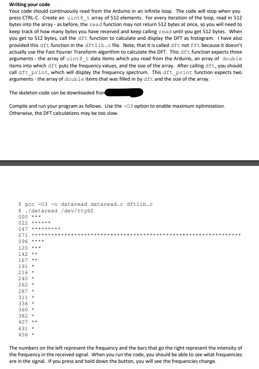

Transcribed Image Text:Writing your code
Your code should continuously read from the Arduino in an infinite loop. The code will stop when you
press CTRL-C. Create an uint8_t array of 512 elements. For every iteration of the loop, read in 512
bytes into the array - as before, the read function may not return 512 bytes at once, so you will need to
keep track of how many bytes you have received and keep calling read until you get 512 bytes. When
you get to 512 bytes, call the dft function to calculate and display the DFT as histogram. I have also
provided this dift function in the dftlib.c file. Note, that it is called dft not fft because it doesn't
actually use the Fast Fourier Transform algorithm to calculate the DFT. This dft function expects three
arguments - the array of uint8_t data items which you read from the Arduino, an array of double
items into which dft puts the frequency values, and the size of the array. After calling dft, you should
call dft_print, which will display the frequency spectrum. This dft_print function expects two
arguments - the array of double items that was filled in by dft and the size of the array.
The skeleton code can be downloaded from
Compile and run your program as follows. Use the -03 option to enable maximum optimization.
Otherwise, the DFT calculations may be too slow.
$ gcc -03 -o dataread dataread.c dftlib.c
$ ./dataread /dev/ttyS2
000
***
022 ******
047 *****
071
096 ****
120 ***
142 **
167 **
191*
216*
240*
262 +
287*
311+
336-
360-
382-
407 --
431 +
456+
The numbers on the left represent the frequency and the bars that go the right represent the intensity of
the frequency in the received signal. When you run the code, you should be able to see what frequencies
are in the signal. If you press and hold down the button, you will see the frequencies change.
![#include <stdio.h>
#include <stdlib.h>
#include <string.h>
#include <unistd.h>
#include <termios.h>
#include <fcntl.h>
void dft(uint8_t*, double*, int);
void dft_print(double*, int, double);
#define N 512
int main(int argc, char **argv)
{
char *port = argv[1];
/* Open the file */
int fd = open(port, O_RDONLY);
// code to set communication rate to 9600 bits per second
struct termios tio;
tcgetattr(fd, &tio);
cfset speed(&tio, B9600);
tcsetattr(fd, 0, &tio);
// reopen the serial port so that the speed change takes effect
close(fd);
fd = open(port, O_RDONLY);
if (fd < 0) {
}
perror("Could not open port");
exit(-1);
uint8_t data[N];
double dftdata[N];
// TODO create a loop that continuously
//
//
reads N bytes from fd into the data array
calls the dft function to create the frequency values
calls the dft_print function to print the DFT
close(fd);
}](https://content.bartleby.com/qna-images/question/d157c2f1-05b6-423a-ba0e-fe1db71475c5/d3c5e46e-8b43-4931-9f77-a8b5843acc34/hjir0k9_processed.png)
Transcribed Image Text:#include <stdio.h>
#include <stdlib.h>
#include <string.h>
#include <unistd.h>
#include <termios.h>
#include <fcntl.h>
void dft(uint8_t*, double*, int);
void dft_print(double*, int, double);
#define N 512
int main(int argc, char **argv)
{
char *port = argv[1];
/* Open the file */
int fd = open(port, O_RDONLY);
// code to set communication rate to 9600 bits per second
struct termios tio;
tcgetattr(fd, &tio);
cfset speed(&tio, B9600);
tcsetattr(fd, 0, &tio);
// reopen the serial port so that the speed change takes effect
close(fd);
fd = open(port, O_RDONLY);
if (fd < 0) {
}
perror("Could not open port");
exit(-1);
uint8_t data[N];
double dftdata[N];
// TODO create a loop that continuously
//
//
reads N bytes from fd into the data array
calls the dft function to create the frequency values
calls the dft_print function to print the DFT
close(fd);
}
SAVE
AI-Generated Solution
info
AI-generated content may present inaccurate or offensive content that does not represent bartleby’s views.
Unlock instant AI solutions
Tap the button
to generate a solution
to generate a solution
Click the button to generate
a solution
a solution
Knowledge Booster

Similar questions
- Create a FSM that works as a sequence detector that receives a bit-serial input X and asserts an output Z (i.e. Z = 1) when it detects a binary string 0110 in sequence of 0s and 1s. You need to provide the following components: 1. Input set A 2. Internal states set S 3. Output set Z 4. Initial state 5. State diagramarrow_forwardA digital combinational circuit has 4 inputs ABCD that represents a 4 bit binary number,(A is the most significant bit). The output of the circuit will be 1 if the input number is a multiple of 4. If the circuit is implemented using 4X1 multiplexer, then which of the given designs is correct. What is required is to select the correct image from these images, or if all of the images are incorrect, design a correct onearrow_forwardYour task is to write code to implement a two-tone siren using the QUTy. You must use one of the Waveform Outputs of TCA0 to drive the buzzer. The buzzer should always be driven with a 50% duty cycle signal. Your siren must alternate between the following frequencies: f1 = 2110 Hz with f1 active for t1 = 370 ms f2 = 4960 Hz with f2 active for t2 = 630 ms main() will call the init() function you write below and then drop into an infinite loop. The init() function you write MUST return to demonstrate your code is interrupt driven. In addition to init(), you may write any code you wish in this file, including ISRs. // NOTe: make sure to use the buffered versions of the CMP/PER registers //! NOTE: DO not use _delay_ms or _delay_us, we want you to do the math //! yourself and make your program interrupt drivenarrow_forward
- A digital counter is a device that generates binary numbers in a specified count sequence. The counter progresses through the specified sequence of numbers when triggered by an incoming clock waveform, and it advances from one number to the next only during the occurrence of a clock pulse. The counter cycles through the same sequence of numbers continuously so long as there is an incoming clock pulse. You are to build a 3-bit synci. us count-down counter, which is a counter that counts down goes throug.. Linnni states 111 to 000 and back to 111 to repeat the cou. are to use a positive-edge-tgered JK flip-flops. In the first step of the design, you ecu .- Flop inputs (1 column for each flip-flop input) The present state pur uv.. design and should enumerate the count sequence. The next state columns should specif wnicn slale wn cuo next, given the present state. For example, if circuit is in a present state of the nevt ate in a down-count sequence would be 0. You should design the FF…arrow_forwardImplement a program to do a bitwise complement (NOT) of an integer number entered by the user. You should use the XOR operator to implement the NOT, do not use the NOT operator. Your program should include a proper and useful prompt for input, and print the results in a meaningful manner. use assembly language to codearrow_forwardTask 4: Application of 7-Segment Display Controller: You are to design a combinational circuit that displays the 7-segment display outputs triggered by the following 2 input combinations. The block diagram of the required design is shown below. Combinational Circuit a) Complete the table below. Inputs Y 7-segments Output (small letter) a e 1 b) Plot the truth table entries in the K-map matrix and simplify. Y X X a = b = C= Y Y X X X d = e = f = g = c) Draw and build the combinational logic circuit below.arrow_forward
- How many clocks does it take for a change in Datain to be reflected on DataOut? module BitReverser ( (); input logic clk, input logic Rst, input logic [7:0] DataIn, output logic [7:0] Dataout assign Dataout [7] = DataIn[0]; assign DataOut [6] = DataIn[1]; assign Dataout [5] = DataIn[2]; assign Dataout [4] = DataIn[3]; assign DataOut [3] = DataIn[4]; assign Dataout [2] = DataIn[5]; assign DataOut [1] = Dat n[6]; assign DataOut[e] = DataIn[7]; endmodule Pick one of the choices 00 01 04 08arrow_forwardDesign a circuit that takes three bits, X2, X1, X0 as input and produces one output, F. F is 1 if and only if 2<=X<=5 when X = (X2, X1, X0) is read as an unsigned integer. For example, if X2=1, X1=0, and X0=0, then the unsigned binary value is 100, which is 4, so the output would be 1. Your Assignment For This Problem Includes the Following Design the necessary circuit using Logisim to implement the situation described above. Use Kmaps for simplification. Be VERY careful to get the correct functions for your output before simplifying and designing the circuit with Logisim. You should minimize the circuit. Your circuit should have three inputs and one LED output. All inputs (X2, X1, X0) and output (F) should be labeled (in Logisim, not by hand). Please use these names to indicate the inputs and output so all projects are consistent. You should also include your name as a label on the circuit. Test your circuit to be sure it is working correctly.arrow_forward
arrow_back_ios
arrow_forward_ios
Recommended textbooks for you
- Database System ConceptsComputer ScienceISBN:9780078022159Author:Abraham Silberschatz Professor, Henry F. Korth, S. SudarshanPublisher:McGraw-Hill Education
 Starting Out with Python (4th Edition)Computer ScienceISBN:9780134444321Author:Tony GaddisPublisher:PEARSON
 Digital Fundamentals (11th Edition)Computer ScienceISBN:9780132737968Author:Thomas L. FloydPublisher:PEARSON
  C How to Program (8th Edition)Computer ScienceISBN:9780133976892Author:Paul J. Deitel, Harvey DeitelPublisher:PEARSON
 Database Systems: Design, Implementation, & Manag...Computer ScienceISBN:9781337627900Author:Carlos Coronel, Steven MorrisPublisher:Cengage Learning
 Programmable Logic ControllersComputer ScienceISBN:9780073373843Author:Frank D. PetruzellaPublisher:McGraw-Hill Education
Database System Concepts
Computer Science
ISBN:9780078022159
Author:Abraham Silberschatz Professor, Henry F. Korth, S. Sudarshan
Publisher:McGraw-Hill Education
Starting Out with Python (4th Edition)
Computer Science
ISBN:9780134444321
Author:Tony Gaddis
Publisher:PEARSON
Digital Fundamentals (11th Edition)
Computer Science
ISBN:9780132737968
Author:Thomas L. Floyd
Publisher:PEARSON
C How to Program (8th Edition)
Computer Science
ISBN:9780133976892
Author:Paul J. Deitel, Harvey Deitel
Publisher:PEARSON
Database Systems: Design, Implementation, & Manag...
Computer Science
ISBN:9781337627900
Author:Carlos Coronel, Steven Morris
Publisher:Cengage Learning
Programmable Logic Controllers
Computer Science
ISBN:9780073373843
Author:Frank D. Petruzella
Publisher:McGraw-Hill Education