Question

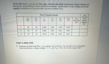
Transcribed Image Text:In the table below, you can see that again, someone has taken current and voltage readings for
the circuit, using different values for the two resistors. In this case, it's the voltage across the
parallel combination of resistors that's given in column VTOT.
1
2
3
R₁
(52)
33
33
47
R₂
(52)
33
47
47
Part 2: Parallel circuits
I
(A)
0.309
0.262
0.215
V₁
(V)
5.00
5.00
5.00
35
5.00
5.00
5.00
VTOT
(V)
5.00
5.00
5.00
Req
(Ohm Law)
(12)
Req
(Using the
rule for
parallel
resistors)
(52)
PART 2 ANALYSIS
6. Examine the data from Part 2. According to the textbook, what should be the relationship
between the three voltage readings: V₁, V₂, and VTOT? How do the data support this?

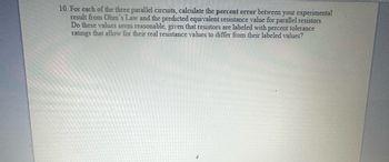
Transcribed Image Text:10. For each of the three parallel circuits, calculate the percent error between your experimental
result from Ohm's Law and the predicted equivalent resistance value for parallel resistors.
Do these values seem reasonable, given that resistors are labeled with percent tolerance
ratings that allow for their real resistance values to differ from their labeled values?
Expert Solution
This question has been solved!
Explore an expertly crafted, step-by-step solution for a thorough understanding of key concepts.
Step by stepSolved in 6 steps with 20 images

Knowledge Booster
Similar questions
- In the circuit below, Vo = 27 V, V₁ = 11 V, R₁ = 8 , & R₂ = 32. Determine the current through R₁, R₂, and the current coming out of V. (Io). R₂ V₁ R₁ Io I₁ = 12 Vo 012 || || ||arrow_forwardFor the circuit given. What is the charge stored on C3, in mC? The voltage source in the circuit has a potential different of 6 V. C1 = 2.42 mF C2= 4.33 mF C3= 6.96 mFarrow_forwardThe drawing shows three different resistors in two different circuits. The battery has voltage of V = 26V, and the resistors have resistances of R one = 50.0, 2 = 25.0 and 3 = 10.0 determine the current through the voltage across each resistor. For circuit you’ll have six parts to the answer: l1,l2,l3, V1, V2, V3. For circut B you will have 6 parts to the answer: l1, l2, l3, V1, V2, V3. arrow_forward
- In the table below, you can see that again, someone has taken current and voltage readings for the circuit, using different values for the two resistors. In this case, it's the voltage across the parallel combination of resistors that's given in column VTOT. 1 2 3 R₁ (52) 33 33 47 R₂ (52) 33 47 47 Part 2: Parallel circuits I (A) 0.309 0.262 0.215 V₁ (V) 5.00 5.00 5.00 35 5.00 5.00 5.00 VTOT (V) 5.00 5.00 5.00 Req (Ohm Law) (12) Req (Using the rule for parallel resistors) (52) PART 2 ANALYSIS 6. Examine the data from Part 2. According to the textbook, what should be the relationship between the three voltage readings: V₁, V₂, and VTOT? How do the data support this?arrow_forwardVoltage (volts) current (mA) 3.00 10.0 6.00 20.0 9.00 29.5 12.00 40.0 1A= 1000 mA Plot a graph of Voltage (y-axis) vs. Current (x-axis.) Draw the straight line of best fit through the points and determine the slope of the line. What is the resistance of the unknown resistor? Answer choices: a) 0.3 ohms b) 30 ohms c) 3 ohms d) 300 ohms e) 333 ohmsarrow_forwardHi everyone, hope you all are doing well. I need help in Physics, please. Regardsarrow_forward
- ? A circuit consisting of three ideal batteries with voltages 1, 82, and 83, and three ideal resistors with resistances R₁, R₂, and R3, is shown in the figure. 81 = 34.0 V, E2 = 15.0 V, 83 = 28.5 V R₁ = 2.90 kn, R₂ = 22.5 k2, R3 = 6.00 k Calculate the current Ip through point P. Let the sign of the current correspond to its direction, with "up" being positive. ww Ip = P R₁ E₁ + + 82 ww R₂ R₂ E3 + mAarrow_forward6 9 == 12 UD 15 10 18 +14 E A B R HI +|1|4 C: E A R +q -9 B www R C +q -9 (a) Original circuit (b) Charging capacitor (b) Discharging capacitor In the attached figure, the RC circuit has been connected to the battery (E=Vo = 12 V) for a long time in the "charging" circuit (switch at A). Suddenly it is switched to the "discharging" circuit (switch at B) and the time is measured from that time. If R = 35 k2and C = 12 mF then calculate the voltage across the capacitor after a time of t = 1400 seconds. Express your answer in volts (V).arrow_forwardB. The circuit at right has three resistors, R1, R2 and R2 connected with two ideal batteries. The three R1 20 Q currents in each leg of the circuit are labeled as ią, ib, and i, as shown. la ic R2 i. Apply Kirchhoff's laws to the circuit and write the three equations that represent the circuit below. 40 Q R3 80 Q + BAT1 9 V ВАТ2 12 V ii. Solve the system of equations to find as ia, ib, and ic. Show your work.arrow_forward
arrow_back_ios
arrow_forward_ios