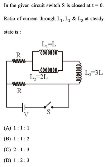
In the given circuit switch S is closed at t = 0. Ratio of current through L₁, L₂ & L3 at steady state is : R R V (A) 1:1:1 (B) 1:1:2 L₁=L “ÞööbbőЖ 0000000 L₂=2L S L₂=3L
Q: For the circuit shown below, E = 26 V, L = 4.8 mH, and R = 4.5 Q. After steady state is reached with…
A: Given ∈=26 VL = 4.8 mHR = 4.5 Ω
Q: PL (mW) For the circuit shown, the power dissipated in the load 60 Resistance RL, is given as a…
A: The value of ResistanceRs.given,diagram,
Q: At 1=0 the switch S is closed with the capacitor uncharged. If C= 30 µF, E = 50 V, and R = 10 k2,…
A: Given The capacitance of the capacitor is C = 30 µF = 30 x 10-6 F. The supply emf is E = 50 V. The…
Q: Having been in position for a long time, the switch in the circuit below is moved to position b at…
A: Here is explanation of the above problem.
Q: If i,(t) = 10 u(t)A a. i̟(0~) =? b. i(t) =?
A: The given circuit is a combination of all passive component viz. Resistance, Inductance and…
Q: PL (mW) For the circuit shown, the power dissipated in the load 60 Resistance RL, is given as a…
A: Given: The graph and circuit are as follows: Introduction: The maximum power transfer occurs when…
Q: A C, A QUESTION 30 In the figure, R=10.0 k2; R₂ = 15.0 k2;C= 0.400 μF; e = 20.0 V. First, the switch…
A: Given:- R1 = 10 kΩ and R2= 15 kΩ C = 0.40μF ε=20 V The circuit as First, the switch is closed for…
Q: For the circuit shown in Fig. Q2(b), assuming the switch has been opened for a very long time, when…
A: The switch was kept opened. hence, the inductor was initially uncharged. When the switch is closed…
Q: For a long period of time the switch S in position "b". At t = 0 s, the switch S moved from position…
A:
Q: Consider the circuit shown. Before the switch is closed, both capacitors are uncharged. V = 12.0 V,…
A: V = 12 volts R1 = 90 Ω R2 = 30 Ω R3 = 60 Ω C1 = 5 × 10-⁶ F C2 = 3×10-⁶ F
Q: . Show that the power loss in transmission lines PL, is givenby PL where is the power transmitted…
A: Given data The power transmitted to the user is PT The delivered voltage is V The resistance of…
Q: An ordinary gold wedding ring is tossed end over end into a running MRI machine with a 4.0 T field.…
A: Write the provided data with the appropriate variables.Here, B is the time spent, R is the…
Q: For V1=78 V, R1=24, R2=28 & C1=0.006 Farrad in the shown circuit, the switch has been closed for a…
A:
Q: In the circuit of the figure & = 1.83 kV, C = 7.20 µF, R1 = R2=R3=D1.02 M2. With C completely…
A: Solution: At t=0, the capacitor is uncharged and the capacitor can be replaced by a wire. On the…
Q: In the figure, e = 94.8 V, R1 = 7.80 Q, R2 = 27.0 Q, R3 = 30.7 Q, and L = 1.65 H. Immediately after…
A: Since we answer up to three subparts, we will answer the first three. Please resubmit the question…
Q: (a) In the figure what value must R have if the current in the circuit is to be 1.3 mA? Take ₁ = 2.7…
A:
Q: ately after switch S is closed A ]A time after S is closed A ately after S is reopened (Assume the…
A:
Q: Problem 6: An RL circuit is shown on the right. L 2.4 H. R 49 Ω.e 7.5 V Part (a) Switch A is closed…
A: When Switch A is closed and B is open, it is a simple RL circuit with a dc voltage source. Thus, the…
Q: The power (p) supplied to an electric circuit is given by wR 2n/w 27 Jo 2 dt. %3D If i=62* I…
A: Given data: P=ωR2π∫02πωi2dt Where, i=62×Isinωt
Q: For the circuit shown in Fig. Q2(b), assuming the switch has been opened for a very long time, when…
A: The figure shows a LR circuit with the following parameters: Resistance, R=6.6kΩ=6600Ω Inductance,…
Q: Find the current in the switch at the same time. The current through the conductor at this time is…
A:
Q: For the circuit shown in Fig. Q2(b), assuming the switch has been opened for a very long time, when…
A: This problem is from Electronics. Please have a good look
Q: 3.00 k2 d E Es 70.0 V 60.0 V 80.0 V R2 4.00 ka 2.00 k2 R
A: Consider the circuit diagram.
Q: R,=R_ R,=R R;=R R=R R3=2R
A: Voltage across R3 is V = 8V
Q: initially, for the circuit shown, the switch S is open and the capacitor is uncharged. The switch S…
A:
Q: A source of alternating e.m.f. 200 sin (@t) is connected to a lamp whose filament has a resistance…
A: To Find: (1) Peak value of current, (2) R.M.S. value of current, Given: E=200sinωtR=1000 Ω
Q: 70 ONOT LO 0OOT UPL 42 14V 13 = 0.97A a O NOT b. 102 DO OT UPL 102 12 INO SIHJ (TYOT LON 80
A:
Q: 1.7 2.1 2.S 2.7 3.0 3.2 33 3.5 3.6 (Q6) For the following electric circuit, the ing data is obtained…
A: Given: RL Ω VL (V) IL mA 10 1 100 20 1.7 83 30 2.1 71 40 2.5 62 50 2.7 55 60 3 50…
Q: Consider a series RC circuit as in Figure below for which R =5.2 MQ, C=3.2 µF, and ɛ=30.0 V. Find…
A: Given data: Resistance,R = 5.2MΩ = 5.2 × 10⁶ Ω Capacitance,C=3. 2 μF = 3.2 x 10⁻⁶ F Voltage ε = 30…
Q: In the figure the ideal battery has emf g= 64 V. the resistances are R= 46 kQ and R2 = 11 kQ, and…
A: Given: Emf=E=64 V Resistances: R1=46 kΩR2=11 kΩ
Q: E: In an A. C. circuit, the flowing current is i = 5 sin (100 t - π/2) A and the potential…
A:
Q: Part 3 Area vs resistance Area Resistance 0.00000041 219.0884762 0.000000162 549.0172546 0.000000102…
A: given , the graph between Area and the Resistance of the wire.
Q: in the circuit shown in the figure, the S switch is closed at t=0 and the capasitors, which are…
A:
Q: For the circuit in Problem 5, calculate the final current flowing through the inductor if the…
A: in this question first of all we find Requivalent and then we find IL by current division.
Q: The oscillating current in an electrical circuit is as follows, where I is measured in amperes and t…
A: Given data, Current I=4sin60πt+cos120πt
Q: 5. In the following circuit, the output Y for all possible inputs A and B is expressed by the truth…
A:
Q: In the circuit of the figure below, R1 = 21 kQ, R2 = 53 kN, L = 82 mH, and the ideal battery has 8 =…
A: (a) the current ibat through the battery.(b) the rate dibat dt.(c) ibat a long time later. Given,…
Q: In the figure, E = 134 V, R₁ -8.500, R₂ = 17.60, R3 = 26.4 02, and L=2.14 H. Immediately after…
A: Given, The voltage, ε=134V Resistances, R1=8.50ΩR2=17.6ΩR3=26.4Ω Inductance, L=2.14H When the source…
Q: A wire of diameter d, length l and resistivity ρ forms a circular loop. A current enters and leaves…
A:
Q: For the circuit shown below, E = 24 V, L = 3.6 mH, and R = 3.0 N. After steady state is reached with…
A: E = 24 volts L = 3.6 mH R = 3 ohm
Step by step
Solved in 2 steps with 2 images