Introductory Circuit Analysis (13th Edition)
13th Edition
ISBN: 9780133923605
Author: Robert L. Boylestad
Publisher: PEARSON
expand_more
expand_more
format_list_bulleted
Question

Transcribed Image Text:**Educational Content on RL Circuits**
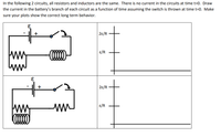
In the following two circuits, all resistors and inductors are the same. Initially, there is no current in the circuits at time \( t=0 \). Your task is to draw the current in the battery's branch of each circuit as a function of time, assuming the switch is thrown at time \( t=0 \). Ensure your plots depict the correct long-term behavior.
### Circuit Diagrams:
#### First Circuit (Top):
- The circuit consists of a battery (\( \epsilon \)), a resistor, an inductor, and a switch.
- Upon closing the switch at \( t=0 \), the current begins to flow, affected by the resistance and inductance.
#### Second Circuit (Bottom):
- Similar to the top circuit, this one also includes a battery (\( \epsilon \)), a resistor, an inductor, and a switch.
- When the switch is closed at \( t=0 \), the behavior mirrors the first circuit initially, with the current developing over time due to the resistance and inductance present.
### Graphs to Illustrate Current Over Time:
For both circuits, the right-hand side contains graphs representing current as a function of time:
- **Vertical Axis (Current):**
- Points marked at \( \frac{2\epsilon}{R} \) and \( \frac{\epsilon}{R} \).
- **Horizontal Axis (Time):**
- Time progresses to the right, showing how current stabilizes over time.
Both circuits display curves that start from zero current and adjust according to the characteristics of the resistor and inductor, illustrating how the current stabilizes to its final value over time. The graphs should show an exponential rise in current as \( t \) increases, ultimately reaching the steady-state where the inductor behaves like a short circuit.
For educational purposes, note how the inductance initially resists changes in current, causing the exponential growth and eventual settling of the current at long-term values.
Expert Solution
This question has been solved!
Explore an expertly crafted, step-by-step solution for a thorough understanding of key concepts.
This is a popular solution
Trending nowThis is a popular solution!
Step by stepSolved in 3 steps with 3 images

Knowledge Booster
Learn more about
Need a deep-dive on the concept behind this application? Look no further. Learn more about this topic, electrical-engineering and related others by exploring similar questions and additional content below.Similar questions
- For the series RL circuit shown in the figure below, answer the following questions and justify your answer.If the current is kept constant, does the coil have inductance?If the current is kept constant, does the coil affect the current value?Can the reverse emf ever be greater than the battery emf?arrow_forwardThe maximum value of an alternating voltage is 300 V. It takes 20 ms for one cycle. So write the formula for alternating voltage and (1) Find the time taken to reach 200 V for the first time after zero, and (2) find the value of the voltage at 18 ms.arrow_forward1-13 Describe Kirchhoff's Voltage Law. Explain how it relates to the principle of the conservation of energy.arrow_forward
- What is the resistance to the changing flow of alternating current? Select one: A. AMPERES B. INDUCTANCE C. REACTANCEarrow_forwardAnswer part (D)arrow_forwardWhen the switch is closed in above circuit, what is the voltage on the inductor, resistor R1 and R2 after 2.2us , assuming 0 V on the inductor to start?arrow_forward
arrow_back_ios
arrow_forward_ios
Recommended textbooks for you
 Introductory Circuit Analysis (13th Edition)Electrical EngineeringISBN:9780133923605Author:Robert L. BoylestadPublisher:PEARSON
 Delmar's Standard Textbook Of ElectricityElectrical EngineeringISBN:9781337900348Author:Stephen L. HermanPublisher:Cengage Learning
 Programmable Logic ControllersElectrical EngineeringISBN:9780073373843Author:Frank D. PetruzellaPublisher:McGraw-Hill Education
 Fundamentals of Electric CircuitsElectrical EngineeringISBN:9780078028229Author:Charles K Alexander, Matthew SadikuPublisher:McGraw-Hill Education
 Electric Circuits. (11th Edition)Electrical EngineeringISBN:9780134746968Author:James W. Nilsson, Susan RiedelPublisher:PEARSON
 Engineering ElectromagneticsElectrical EngineeringISBN:9780078028151Author:Hayt, William H. (william Hart), Jr, BUCK, John A.Publisher:Mcgraw-hill Education,

Introductory Circuit Analysis (13th Edition)
Electrical Engineering
ISBN:9780133923605
Author:Robert L. Boylestad
Publisher:PEARSON

Delmar's Standard Textbook Of Electricity
Electrical Engineering
ISBN:9781337900348
Author:Stephen L. Herman
Publisher:Cengage Learning

Programmable Logic Controllers
Electrical Engineering
ISBN:9780073373843
Author:Frank D. Petruzella
Publisher:McGraw-Hill Education

Fundamentals of Electric Circuits
Electrical Engineering
ISBN:9780078028229
Author:Charles K Alexander, Matthew Sadiku
Publisher:McGraw-Hill Education

Electric Circuits. (11th Edition)
Electrical Engineering
ISBN:9780134746968
Author:James W. Nilsson, Susan Riedel
Publisher:PEARSON

Engineering Electromagnetics
Electrical Engineering
ISBN:9780078028151
Author:Hayt, William H. (william Hart), Jr, BUCK, John A.
Publisher:Mcgraw-hill Education,