Question
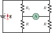
In the figure R1 = 3.59R, the ammeter resistance is zero, and the battery is ideal. What multiple of ε/R gives the current in the ammeter?

Transcribed Image Text:R1
A
R
Expert Solution
This question has been solved!
Explore an expertly crafted, step-by-step solution for a thorough understanding of key concepts.
This is a popular solution
Trending nowThis is a popular solution!
Step by stepSolved in 4 steps with 4 images

Knowledge Booster
Similar questions
- A cylindrical conductor with resistivity ρ, length L, and radius r , has resistance R0=302Ω. If the resistivity and the length of the conductor both have their original values, but instead the radius of the conductor is increased by a factor of 5, what is the new value, in ohms, of the resistance?arrow_forwardThe two figure panels show two ways to connect a real (non-ideal) voltmeter and a real ammeter in a circuit to calculate the resistance R. The internal resistance of the voltmeter is Rv and the internal resistance of the ammeter is Ra. The current flows from left to right in both panels, and the potential difference Vac between points a and c in both panels is the same. In panel (a) the voltmeter reads Vac = 12.1 V and the ammeter reads I1 = 0.098 A. In panel (b) the voltmeter reads Vab = 12.0 V and the ammeter reads I2 = 0.100 A. I need help with Part E.arrow_forwardConsider the circuit shown in the figure below, where R, = 8.00 N, R, = 7.00 N, and Ɛ = 11.0 V. %3D 10.0 N R2 5.00 N 2.00 N R1 (a) Find the voltage (in V) across R,. V (b) Find the current (in A) in R,. Aarrow_forward
- In the schematic below two batteries are in series and drive current through the circuit as shown. The first resistor has a voltage drop AV = 2.8 V, the middle resistor has a resistance of R = 154 Q, and the last resistor has a voltage drop AV2 = 1.6 V. Given these parameters, what is the magnitude of current flowing through the circuit in milli-amps (mA)? Giver your answer to 3 significant figures. %3D AV, 3.0 V 4.5 V wwarrow_forwardThe potential difference across a resistor in a particular electric circuit is 360 V. The current through the resistor is 10.0 A. What is its resistance (in )? Qarrow_forwardHow to solve for the following:arrow_forward
- Problem 5: A current of I- 2.6 A passes through the circuit shown, where R- 65 3R 5R V) 2R 6R 2R 7R 5R 10R Otheexpertta.com Part (a) In terms of R, I, and numeric values, write an expression for the voltage of the · source, V. Part (b) What is the voltage, V in volts? tan( sin() cotanO a acos cosh0t cosO asin() acotan 4 5 6 sinh() cotanhO *1 23 0 tanh0c O Degrees O Radians CLEAR BACKSPACEarrow_forwardResistance, R, is defined using R = V/I where V is the potential across a resistor, and I is thecurrent. R is measured in ohms (Ω), where 1 Ω = 1 V/A. The constant you determined in eachequation should be similar to the resistance of each resistor. However, resistors aremanufactured such that their actual value is within a tolerance. For many common resistors, thetolerance is 5% or 10%. Calculate the range of possible values for each resistor. Does the constant in each equation fit within the appropriate range of values for each resistor? Do the resistors follow Ohm’s law? Base your answer on your experimental data. Slope (V/A) Y-intercept (V) Resistor 10 Ω 9.896V/A 0.0005526V Resistor 51 Ω 50.91V/A 0.01030V Light bulb (first 3 pts) 5.386V/A n/a Light bulb (last 10 pts) 43.26V/A n/aarrow_forwardYou have a circuit consisting of a power supply, switch, resistor, two capacitors, and voltage/current probes. The resistor has the value R1 = (1.8 ± 10%) MQ. The capacitors have %3D the values C1 = (0.6 ± 20%) µF and C2 = (2.2 ± 20%) µF. The logger pro data resembles the plot below. 40 35 30 25 20 15 10 1 2 3 5 6 8 9 10 11 12 13 14 15 16 17 18 19 20 21 22 23 24 25 a) Label the title and all the axes on the plot above. Identify which region corresponds to the capacitors charging and discharging. Be sure to include appropriate units (MKS).arrow_forward
arrow_back_ios
arrow_forward_ios