
Introductory Circuit Analysis (13th Edition)
13th Edition
ISBN: 9780133923605
Author: Robert L. Boylestad
Publisher: PEARSON
expand_more
expand_more
format_list_bulleted
Related questions
Question
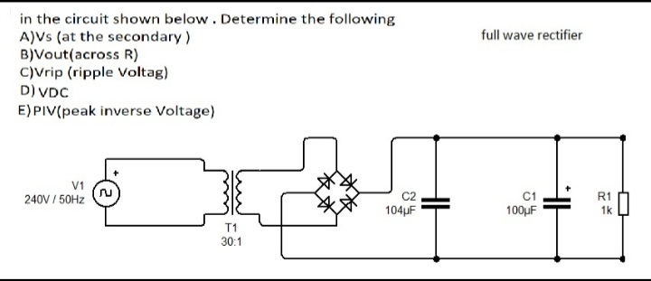

Transcribed Image Text:in the circuit shown below. Determine the following
A)Vs (at the secondary)
B)Vout(across R)
C)Vrip (ripple Voltag)
D) VDC
full wave rectifier
E) PIV(peak inverse Voltage)
V1
C1
100µF
240V / 50HZ
R1
104µF
1k
T1
30:1
Expert Solution
This question has been solved!
Explore an expertly crafted, step-by-step solution for a thorough understanding of key concepts.

Step by stepSolved in 4 steps with 4 images

Knowledge Booster


Learn more about
Need a deep-dive on the concept behind this application? Look no further. Learn more about this topic, electrical-engineering and related others by exploring similar questions and additional content below.Similar questions
- 5. The bridge rectifier shown in Figure 2 uses ideal diodes. The input voltage is 24V. Find: a. DC output voltage b. Sketch the output waveform D2 D3 R = 12 k2 %3D DA Di 000arrow_forwardMust answer for both circuits. Dont say only one will be answered.arrow_forwardPower supply circuit is delivering 0.5 A and an average voltage 20 V to the load as shown in the circuit below. The ripple voltage of the half wave rectifier is 0.5 V and the diode is represented using constant voltage model. The smoothing capacitor value is equal to 220V rmsh soHz} VL-DC =20V 0.01 F 0.02 F 0.0167 F None of the abovearrow_forward
- 1) The following is not an example of a Thyristor a) A Silicon Unilateral Switch b) A TRIAC c) A Silicon Controlled Rectifier d) Amorphous Limpid Trilateral Rodomontadearrow_forwardIn diode rectifiers, a. the average output of a HWR is greater than the average output of FWR b. the average output of a FWR is greater than the average output of HWR C. the PIV of a HWR is greater than the average output of center-tapped FWR d. the PIV of a bridge FWR is greater than the average output of center-tapped FWRarrow_forwardIf the input waveform of a half wave rectifier frequency is 50HZ, then the output waveform frequency will be. . .Hz О 50 О 100 O 25 O 75 O not all abovearrow_forward
- If the ripple factor of a rectifier is 30% for an average voltage of 2V, its ripple rms voltage (VrRMS) will be 0.6mV 0.6 V 9.67 mV 0.7 Varrow_forward89. If the ripple voltage in a full-wave rectifier is 25 V at a load current of 60 mA, its value at a load current of 120 mA will be (i) 50 V (ii) 25 V (iii) 100 V (iv) 12.5 Varrow_forwardIn the circuit shown below. Determine the following a. Vs (at the secondary) b. Vout (across RL) c. Vrip (ripple votage) d. VDC e. PIV (Peak Inverse Voltage) 10:1 Output 115 V mis 60 Hz RL 2.2 k) D, 50μF- All diodes are IN4001. Tund AlMannai EENG261 Page 5/11arrow_forward
- When a sinusoidal voltage at 60 Hz is applied to the input of a half-wave rectifier, the output frequency is: (a) 120Hz (b) 30Hz (c) 60Hz (d) 0Hzarrow_forwardIn a full wave bridge rectifier, if one diode is damage, this gives: A) The circuit will not work 7 B) Input and output frequency will remind the same C) The Peak Inverse Voltage is equal to output voltage D) No current will pass though the circuitarrow_forwardier quesuon Will save this response. Quèstion 6 Power supply circuit is delivering 0.5 A and an average voltage 20 V to the load as shown in the circuit below. The ripple voltage of the half wave rectifier is 0.5 V and the diode is represented using constant voltage model. The smoothing capacitor value is equal to iL-DC =05A RL VLDC =20V 220V omsb 0.01 F 0.02 F 0.0167 F Hows b None of the above DEV Chparrow_forward
arrow_back_ios
SEE MORE QUESTIONS
arrow_forward_ios
Recommended textbooks for you
- Introductory Circuit Analysis (13th Edition)Electrical EngineeringISBN:9780133923605Author:Robert L. BoylestadPublisher:PEARSON
 Delmar's Standard Textbook Of ElectricityElectrical EngineeringISBN:9781337900348Author:Stephen L. HermanPublisher:Cengage Learning
 Programmable Logic ControllersElectrical EngineeringISBN:9780073373843Author:Frank D. PetruzellaPublisher:McGraw-Hill Education
  Fundamentals of Electric CircuitsElectrical EngineeringISBN:9780078028229Author:Charles K Alexander, Matthew SadikuPublisher:McGraw-Hill Education
 Electric Circuits. (11th Edition)Electrical EngineeringISBN:9780134746968Author:James W. Nilsson, Susan RiedelPublisher:PEARSON
 Engineering ElectromagneticsElectrical EngineeringISBN:9780078028151Author:Hayt, William H. (william Hart), Jr, BUCK, John A.Publisher:Mcgraw-hill Education,
Introductory Circuit Analysis (13th Edition)
Electrical Engineering
ISBN:9780133923605
Author:Robert L. Boylestad
Publisher:PEARSON
Delmar's Standard Textbook Of Electricity
Electrical Engineering
ISBN:9781337900348
Author:Stephen L. Herman
Publisher:Cengage Learning
Programmable Logic Controllers
Electrical Engineering
ISBN:9780073373843
Author:Frank D. Petruzella
Publisher:McGraw-Hill Education
Fundamentals of Electric Circuits
Electrical Engineering
ISBN:9780078028229
Author:Charles K Alexander, Matthew Sadiku
Publisher:McGraw-Hill Education
Electric Circuits. (11th Edition)
Electrical Engineering
ISBN:9780134746968
Author:James W. Nilsson, Susan Riedel
Publisher:PEARSON
Engineering Electromagnetics
Electrical Engineering
ISBN:9780078028151
Author:Hayt, William H. (william Hart), Jr, BUCK, John A.
Publisher:Mcgraw-hill Education,