
Introductory Circuit Analysis (13th Edition)
13th Edition
ISBN: 9780133923605
Author: Robert L. Boylestad
Publisher: PEARSON
expand_more
expand_more
format_list_bulleted
Related questions
Question

Transcribed Image Text:W
R
ɛ
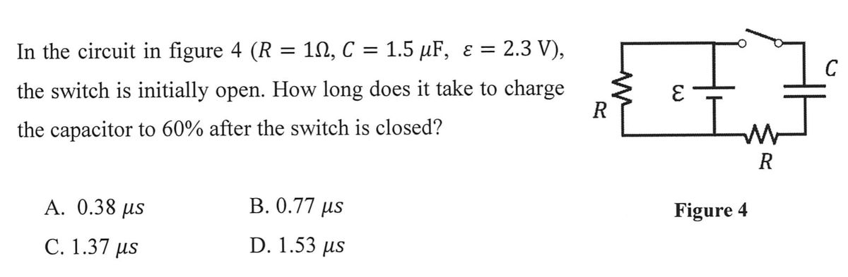
In the circuit in figure 4 (R = 10, C = 1.5 μF, ε = 2.3 V),
the switch is initially open. How long does it take to charge
the capacitor to 60% after the switch is closed?
A. 0.38 μs
C. 1.37 μs
B. 0.77 µs
D. 1.53 us
3
W
R
Figure 4
C
Expert Solution
This question has been solved!
Explore an expertly crafted, step-by-step solution for a thorough understanding of key concepts.

Step by stepSolved in 3 steps with 2 images

Knowledge Booster


Learn more about
Need a deep-dive on the concept behind this application? Look no further. Learn more about this topic, electrical-engineering and related others by exploring similar questions and additional content below.Similar questions
- A 10 μF, a 15µF, and a 100µF capacitor are connected in parallel across 50V source. Determine the following: Charge on each capacitor. Write the answer in mCarrow_forwardRefer to Figure If 50V is applied across the capacitors, determine Q. Write the answer in mC 30 μF 60 µF 20 µF ▬HE HE C₁ C2 C 3 -arrow_forwardInductors store energy in an electric field a magnetic field O it does not store energy at all O a coil of wire and proportional to the lengtharrow_forward
- A 90-mF capacitor is charged completely through a 60-Ω resistor. How long will it take for the capacitor to lose 80% of its energy?arrow_forwardThe figure displays two circuits with a charged capacitor that is to be discharged through a resistor when a switch is closed. In figure (a) below, R₁ = 23.32 and C₁ = 5.04 μF. In figure (b) below, R2 = 10.82 and C₂ = 8.10 μF. The ratio of the initial charges on the two capacitors is 902/901 = 1.61. At time t = 0, both switches are closed. At what time t do the two capacitors have the same charge? 0.0 (a) (b) Number i Unitsarrow_forwardIn the circuit shown in the following figure(Figure 1) the capacitor has capacitance 19μF and is initially uncharged. The resistor Ro has resistance 11 2. An emf of 84.0 V is added in series with the capacitor and the resistor. The emf is placed between the capacitor and the switch, with the positive terminal of the emf adjacent to the capacitor. The small circuit is not connected in any way to the large one. The wire of the small circuit has a resistance of 1.1 /m and contains 25 loops. The large circuit is a rectangle 2.0 m by 4.0 m, while the small one has dimensions a = 13.0 cm and b = 18.0 cm. The distance c is 5.0 cm. (The figure is not drawn to scale.) Both circuits are held stationary. Assume that only the wire nearest the small circuit produces an appreciable magnetic field through it. Part A The switch is closed at t = 0. When the current in the large circuit is 4.70 A, what is the magnitude of the induced current in the small circuit? Express your answer with the appropriate…arrow_forward
- In the figure the potential difference V of the battery is 10V. Each capacitor C has a value C = 10 μF. What is the charge on the capacitor C1.arrow_forwardThe energy required to charge a 10 µF capacitor to 100 V is a) 0.1 J b) 0.05 J c) 5 x 10(-9) d) 10 x 10(-9) Jarrow_forwardFind the total capacitance for all 5 circuits. Do not forget units. C21 C1 1µF 1µF C3 C4 C5 1µF 1µF 1µF C6 C7 C2 1µF 1µF 1µF Figure 2 C8 Figure 1 1µF Figure 3 HE HE HE HE HHarrow_forward
- When the switch is in position 1, the circuit will charge the capacitor. Find the Thevenin Equivalent Circuit for the charge phase and determine the time constant (Rh*C) for the charge phase.arrow_forwardplz answer in details, thanks...arrow_forwardIn the box below, show that the time constant r is the time it takes the voltage across a charging capacitor to reach the value (1-1/e)Vmaxarrow_forward
arrow_back_ios
SEE MORE QUESTIONS
arrow_forward_ios
Recommended textbooks for you
- Introductory Circuit Analysis (13th Edition)Electrical EngineeringISBN:9780133923605Author:Robert L. BoylestadPublisher:PEARSON
 Delmar's Standard Textbook Of ElectricityElectrical EngineeringISBN:9781337900348Author:Stephen L. HermanPublisher:Cengage Learning
 Programmable Logic ControllersElectrical EngineeringISBN:9780073373843Author:Frank D. PetruzellaPublisher:McGraw-Hill Education
  Fundamentals of Electric CircuitsElectrical EngineeringISBN:9780078028229Author:Charles K Alexander, Matthew SadikuPublisher:McGraw-Hill Education
 Electric Circuits. (11th Edition)Electrical EngineeringISBN:9780134746968Author:James W. Nilsson, Susan RiedelPublisher:PEARSON
 Engineering ElectromagneticsElectrical EngineeringISBN:9780078028151Author:Hayt, William H. (william Hart), Jr, BUCK, John A.Publisher:Mcgraw-hill Education,
Introductory Circuit Analysis (13th Edition)
Electrical Engineering
ISBN:9780133923605
Author:Robert L. Boylestad
Publisher:PEARSON
Delmar's Standard Textbook Of Electricity
Electrical Engineering
ISBN:9781337900348
Author:Stephen L. Herman
Publisher:Cengage Learning
Programmable Logic Controllers
Electrical Engineering
ISBN:9780073373843
Author:Frank D. Petruzella
Publisher:McGraw-Hill Education
Fundamentals of Electric Circuits
Electrical Engineering
ISBN:9780078028229
Author:Charles K Alexander, Matthew Sadiku
Publisher:McGraw-Hill Education
Electric Circuits. (11th Edition)
Electrical Engineering
ISBN:9780134746968
Author:James W. Nilsson, Susan Riedel
Publisher:PEARSON
Engineering Electromagnetics
Electrical Engineering
ISBN:9780078028151
Author:Hayt, William H. (william Hart), Jr, BUCK, John A.
Publisher:Mcgraw-hill Education,