Introductory Circuit Analysis (13th Edition)
13th Edition
ISBN: 9780133923605
Author: Robert L. Boylestad
Publisher: PEARSON
expand_more
expand_more
format_list_bulleted
Question
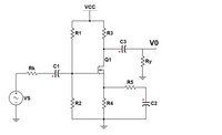
In the circuit given in the figure, Rk = 1.93Kohm, R1 = 2071.88Kohm, R2 = 1678.12Kohm, R3 = 2.84Kohm, R4 = 0.95Kohm, R5 = 26.02ohm, Ry = 95.53Kohm, VCC = 15.00V, VTN = 2.40V, Kn = Since it is 2.30(mA/V^2), C1= 5.80uF, C2= 5.20uF, C3= 7.73uF, calculate the lower cutoff frequency of the circuit in Hz.

Transcribed Image Text:R1
R3
vo
C3
Q1
C1
Rk
R5
vs
R2
R4
C2
Expert Solution
This question has been solved!
Explore an expertly crafted, step-by-step solution for a thorough understanding of key concepts.
Step by stepSolved in 6 steps with 6 images

Knowledge Booster
Learn more about
Need a deep-dive on the concept behind this application? Look no further. Learn more about this topic, electrical-engineering and related others by exploring similar questions and additional content below.Similar questions
- For the circuit diagram in figure Q22: which of the following is the total impedance? 12 Ri 10R R2||5R Figure Q22 V 220V40 50HZ L1 315mH C1=350uF O a. 3.33/0° O b. 4.71290°2 O c. 7.3304-19.66° O d. 10.37261.19°2arrow_forwardIn a transistor if B = 100 and collector current is 10 mA, then IE is * 100 mA 10.1 mA 110 mA none of the abovearrow_forwardPI) Three resistors R,,Rz and Rg are GNnectad in series to a leov Suppky If R=l002,12=250mA and V3-4or, Calcntata a) V b)Re 9Rg. (Ans:25 vs l40 allon)arrow_forward
- Calculate the base current IB in uA when VCC=19V, VEE=-15V , RB=8808 ohm, RC=14798ohm, RE=11126ohm and B=134arrow_forwardIn DC / DC switching circuits, a resistor-inductance (r-l) circuit is usually connected to the load in series, and also a reverse parallel switching diode is connected to this inductance (l). Write down your comments and approaches about the purpose for which these connected resistance, inductance and diode elements are used by an engineer's approacharrow_forwardPLEASE ANSWER THIS MCQarrow_forward
- Figure shows a transistor switching circuit. Find the Vcc and Rc, which causes the output voltage to have a peak to peak value of 6V (given that the input voltage signal Vi, and the output voltage signal Vo, have units of Volt) Fone: V₁ 10k2 www +Vcc Rc V₂ B-100arrow_forwardwhat is the Rin, Rout, gain in given figurearrow_forwardSketch out the fellowing signals: (a=7, b=5, c=8) a-) V = 15a(sin2r1000*ct) b-) V = 3b(cos(7500*ct)+3) c-) Assume that you measure the signal V1 using Digital Volt Meter(DVM) and ossiloscope. What will you read on the DVM display and oscilloscop dispaly when the input voltages are defined as 1-) V = 15a(sin2m1000*ct) 2-) V = 3b(cos(7500*ct)+3) Write down and sketch all the voltages for each case. Show all parameters, including period and maximum values of the signals. aR V AC aR V, aR What will you read at the DVM display when you read the voltages at AC mode What will you read at the DVM display when you read the voltages at DC rangearrow_forward
arrow_back_ios
SEE MORE QUESTIONS
arrow_forward_ios
Recommended textbooks for you
 Introductory Circuit Analysis (13th Edition)Electrical EngineeringISBN:9780133923605Author:Robert L. BoylestadPublisher:PEARSON
 Delmar's Standard Textbook Of ElectricityElectrical EngineeringISBN:9781337900348Author:Stephen L. HermanPublisher:Cengage Learning
 Programmable Logic ControllersElectrical EngineeringISBN:9780073373843Author:Frank D. PetruzellaPublisher:McGraw-Hill Education
 Fundamentals of Electric CircuitsElectrical EngineeringISBN:9780078028229Author:Charles K Alexander, Matthew SadikuPublisher:McGraw-Hill Education
 Electric Circuits. (11th Edition)Electrical EngineeringISBN:9780134746968Author:James W. Nilsson, Susan RiedelPublisher:PEARSON
 Engineering ElectromagneticsElectrical EngineeringISBN:9780078028151Author:Hayt, William H. (william Hart), Jr, BUCK, John A.Publisher:Mcgraw-hill Education,

Introductory Circuit Analysis (13th Edition)
Electrical Engineering
ISBN:9780133923605
Author:Robert L. Boylestad
Publisher:PEARSON

Delmar's Standard Textbook Of Electricity
Electrical Engineering
ISBN:9781337900348
Author:Stephen L. Herman
Publisher:Cengage Learning

Programmable Logic Controllers
Electrical Engineering
ISBN:9780073373843
Author:Frank D. Petruzella
Publisher:McGraw-Hill Education

Fundamentals of Electric Circuits
Electrical Engineering
ISBN:9780078028229
Author:Charles K Alexander, Matthew Sadiku
Publisher:McGraw-Hill Education

Electric Circuits. (11th Edition)
Electrical Engineering
ISBN:9780134746968
Author:James W. Nilsson, Susan Riedel
Publisher:PEARSON

Engineering Electromagnetics
Electrical Engineering
ISBN:9780078028151
Author:Hayt, William H. (william Hart), Jr, BUCK, John A.
Publisher:Mcgraw-hill Education,