
Introductory Circuit Analysis (13th Edition)
13th Edition
ISBN: 9780133923605
Author: Robert L. Boylestad
Publisher: PEARSON
expand_more
expand_more
format_list_bulleted
Related questions
Concept explainers
Question
1.

Transcribed Image Text:### Electrical Circuit Analysis: Step-by-Step Evaluation
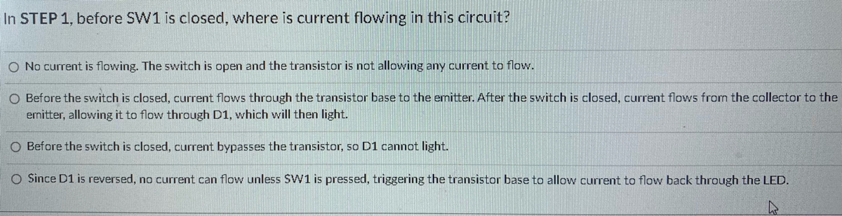
**Question: In STEP 1, before SW1 is closed, where is current flowing in this circuit?**
1. **No current is flowing. The switch is open and the transistor is not allowing any current to flow.**
2. **Before the switch is closed, current flows through the transistor base to the emitter. After the switch is closed, current flows from the collector to the emitter, allowing it to flow through D1, which will then light.**
3. **Before the switch is closed, current bypasses the transistor, so D1 cannot light.**
4. **Since D1 is reversed, no current can flow unless SW1 is pressed, triggering the transistor base to allow current to flow back through the LED.**
---
### Explanation of Circuit Components:
- **SW1 (Switch 1)**: This component controls the flow of current within the circuit. When SW1 is open, it prevents current from flowing.
- **Transistor**: A semiconductor device used to amplify or switch electronic signals. It has three terminals: base, collector, and emitter.
- **D1 (Diode 1)**: Typically an LED (Light Emitting Diode) in this context, which will light up when current flows through it in the correct direction.
In Step 1, an analysis of the circuit indicates that no current is flowing because SW1 is open. This state prevents the transistor from allowing any current to pass, ensuring that no part of the circuit is active.
For further study, it would be beneficial to understand the role of each component under different conditions, such as when the switch is closed and how the transistor influences current flow.

Transcribed Image Text:**Title: Basic Transistor Switch Circuit Diagram**
**Introduction:**
This page provides a detailed explanation of a basic transistor switch circuit, ideal for students and enthusiasts learning about electronics.
**Circuit Description:**
The circuit diagram shown represents a simple transistor switch used to control an LED. The components and their values are outlined as follows:
**Components:**
1. **Power Supply Block (PSB):** 5V power source.
2. **Resistor R1:** 10 kΩ resistor connected in series with the base of the transistor.
3. **Resistor R2:** 1 kΩ resistor connected in series with the LED.
4. **SW1:** Switch used to control the base current to the transistor.
5. **D1:** Green LED.
6. **Q1:** NPN transistor (2N2222).
**Circuit Operation:**
1. **Power Source:** The 5V power supply (PSB) provides the necessary voltage to the circuit.
2. **Base Resistor (R1):** When switch SW1 is closed, a voltage is applied to the base of the transistor Q1 through a 10 kΩ resistor (R1). This resistor limits the base current to a safe level to avoid damaging the transistor.
3. **Switch (SW1):** Controls the connection of the base of transistor Q1 to the power supply.
4. **Transistor (Q1):** The 2N2222 NPN transistor acts as a switch. When SW1 is closed, the base current flows through R1 into the base of the transistor, turning it on. This allows current to flow from the collector to the emitter.
5. **Collector Resistor (R2):** The 1 kΩ resistor (R2) in series with the LED (D1) limits the current flowing through the LED.
6. **LED (D1):** The green LED illuminates when current flows through it, indicating that the transistor Q1 is conducting.
**Summary:**
When SW1 is closed, the base current activates transistor Q1, allowing current to flow from the collector to the emitter. This current passes through the 1 kΩ resistor (R2) and the green LED (D1), causing the LED to light up. Thus, this circuit demonstrates the basic operation of a transistor switch, used to control the illumination of an LED.
By understanding this simple configuration, students can grasp the fundamental principles
Expert Solution
This question has been solved!
Explore an expertly crafted, step-by-step solution for a thorough understanding of key concepts.

This is a popular solution

Trending nowThis is a popular solution!

Step by stepSolved in 2 steps with 2 images

Knowledge Booster


Learn more about
Need a deep-dive on the concept behind this application? Look no further. Learn more about this topic, electrical-engineering and related others by exploring similar questions and additional content below.Similar questions
- Only one of them pleasearrow_forward4. Which of the following is the correct relationship between temperature (T) and mobility (u) of electrons in electronic circuits? a) u - T-3/2 b) u & T-1/2 x c) u - T d) u - T-1arrow_forwardWhat is the dynamic resistance (in Ohms) of a diode if its ID = 4.99 mA? No need for a solution. Just write your numeric answer on the space provided. Round off your answer to 2 decimal places.arrow_forward
arrow_back_ios
arrow_forward_ios
Recommended textbooks for you
- Introductory Circuit Analysis (13th Edition)Electrical EngineeringISBN:9780133923605Author:Robert L. BoylestadPublisher:PEARSON
 Delmar's Standard Textbook Of ElectricityElectrical EngineeringISBN:9781337900348Author:Stephen L. HermanPublisher:Cengage Learning
 Programmable Logic ControllersElectrical EngineeringISBN:9780073373843Author:Frank D. PetruzellaPublisher:McGraw-Hill Education
  Fundamentals of Electric CircuitsElectrical EngineeringISBN:9780078028229Author:Charles K Alexander, Matthew SadikuPublisher:McGraw-Hill Education
 Electric Circuits. (11th Edition)Electrical EngineeringISBN:9780134746968Author:James W. Nilsson, Susan RiedelPublisher:PEARSON
 Engineering ElectromagneticsElectrical EngineeringISBN:9780078028151Author:Hayt, William H. (william Hart), Jr, BUCK, John A.Publisher:Mcgraw-hill Education,
Introductory Circuit Analysis (13th Edition)
Electrical Engineering
ISBN:9780133923605
Author:Robert L. Boylestad
Publisher:PEARSON
Delmar's Standard Textbook Of Electricity
Electrical Engineering
ISBN:9781337900348
Author:Stephen L. Herman
Publisher:Cengage Learning
Programmable Logic Controllers
Electrical Engineering
ISBN:9780073373843
Author:Frank D. Petruzella
Publisher:McGraw-Hill Education
Fundamentals of Electric Circuits
Electrical Engineering
ISBN:9780078028229
Author:Charles K Alexander, Matthew Sadiku
Publisher:McGraw-Hill Education
Electric Circuits. (11th Edition)
Electrical Engineering
ISBN:9780134746968
Author:James W. Nilsson, Susan Riedel
Publisher:PEARSON
Engineering Electromagnetics
Electrical Engineering
ISBN:9780078028151
Author:Hayt, William H. (william Hart), Jr, BUCK, John A.
Publisher:Mcgraw-hill Education,