
Introductory Circuit Analysis (13th Edition)
13th Edition
ISBN: 9780133923605
Author: Robert L. Boylestad
Publisher: PEARSON
expand_more
expand_more
format_list_bulleted
Related questions
Concept explainers
Question
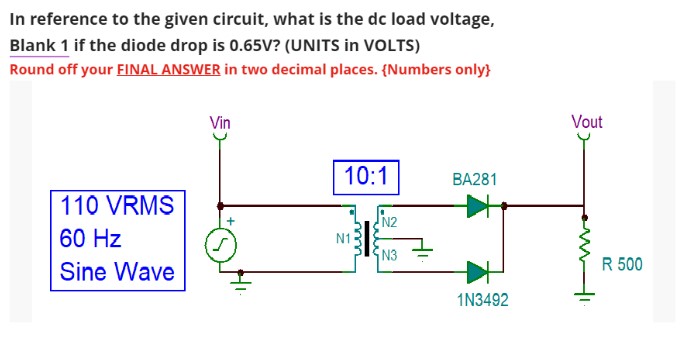

Transcribed Image Text:In reference to the given circuit, what is the dc load voltage,
Blank 1 if the diode drop is 0.65V? (UNITS in VOLTS)
Round off your FINAL ANSWER in two decimal places. {Numbers only}
110 VRMS
60 Hz
Sine Wave
Vin
S
10:1
N1
N2
N3
BA281
1N3492
Vout
R 500
Expert Solution
This question has been solved!
Explore an expertly crafted, step-by-step solution for a thorough understanding of key concepts.

Step by stepSolved in 2 steps with 2 images

Knowledge Booster


Learn more about
Need a deep-dive on the concept behind this application? Look no further. Learn more about this topic, electrical-engineering and related others by exploring similar questions and additional content below.Similar questions
- C) For the circuit below, determine: a. The total peak secondary voltage b. Sketch the voltage waveform across RL, where R1. equals to ETEA Q. c. The peak current through each diode 4:1 100 V rms RL V out elll elllarrow_forward8. You're installing type AC cable. The armor coating of type AC cable is allowed for use as an equipmentgrounding conductor (EGC) because of itsA. liquid-tight fittings listed for EGC purposes.B. interlocking ribs that form a complete circuit.C. internal bare bonding strip.D. internal bare aluminum bonding conductor.arrow_forward1. After the temperature rises, in the pure semiconductor ( ) A. The number of free electrons and holes increases with the same increment B. More holes, same number of free electrons C. Free electrons increase, holes remain unchanged D. The number of free electrons and holes remains unchangedarrow_forward
- Draw the output waveform for the given circuit diagram with proper values and also mention the name of the circuit. The input waveform Vi is having a peak-to-peak value of 17 V and the bias voltage is 4 V. Assume diode to be silicon. Vo Maximum value of output waveform Minimum voltage of output waveformarrow_forwardR₁ 54 R₂ D₁ ▷ Figure 1: Precision Rectifier 1. Characterize the relationship of input vs. output for the circuit in Figure 1. That is, find an expression for e. You can use the constant voltage drop model for the diodes. VIarrow_forwardQ3: The figure below includes a bridge full-wave rectifier circuit with a diode type is1N4007. The input voltage is Vin V2 120 sin 2n60t 5:1 D3 D1 120 V RL Vp(out) D2 DA 10 kN a) Draw the output voltage waveform for the circuit in the figure and include thevoltage values. b) What is the peak inverse voltage (PIV) across each diode? c) Determine the rms voltage, current and power delivered to RL d) Determine the average voltage, current, and power delivered to RL e) What is the ratio of Po(de) to Po(ac)? lllarrow_forward
- shown below is a diode circuit. If the input signal Vs= 36Vp-p and the DC voltage Vdc = 4V, what is the output voltage (in volts) of the circuit during the positive alteration?arrow_forward1. What is a generic diode and when it was invented? please provide an original response, thank youarrow_forwardThe input to a 3-phase full-wave rectifier is 60 Hz AC voltage. If the voltage drop across diodes is 0 V, The RMS voltage at the load would be: O A. None of the other choices are correct O B. Cannot tell until we have more information O C. Lower than the RMS voltage at the input O D. Higher than the RMS voltage at the input O E. The same as the RMS voltage at the inputarrow_forward
arrow_back_ios
arrow_forward_ios
Recommended textbooks for you
- Introductory Circuit Analysis (13th Edition)Electrical EngineeringISBN:9780133923605Author:Robert L. BoylestadPublisher:PEARSON
 Delmar's Standard Textbook Of ElectricityElectrical EngineeringISBN:9781337900348Author:Stephen L. HermanPublisher:Cengage Learning
 Programmable Logic ControllersElectrical EngineeringISBN:9780073373843Author:Frank D. PetruzellaPublisher:McGraw-Hill Education
  Fundamentals of Electric CircuitsElectrical EngineeringISBN:9780078028229Author:Charles K Alexander, Matthew SadikuPublisher:McGraw-Hill Education
 Electric Circuits. (11th Edition)Electrical EngineeringISBN:9780134746968Author:James W. Nilsson, Susan RiedelPublisher:PEARSON
 Engineering ElectromagneticsElectrical EngineeringISBN:9780078028151Author:Hayt, William H. (william Hart), Jr, BUCK, John A.Publisher:Mcgraw-hill Education,
Introductory Circuit Analysis (13th Edition)
Electrical Engineering
ISBN:9780133923605
Author:Robert L. Boylestad
Publisher:PEARSON
Delmar's Standard Textbook Of Electricity
Electrical Engineering
ISBN:9781337900348
Author:Stephen L. Herman
Publisher:Cengage Learning
Programmable Logic Controllers
Electrical Engineering
ISBN:9780073373843
Author:Frank D. Petruzella
Publisher:McGraw-Hill Education
Fundamentals of Electric Circuits
Electrical Engineering
ISBN:9780078028229
Author:Charles K Alexander, Matthew Sadiku
Publisher:McGraw-Hill Education
Electric Circuits. (11th Edition)
Electrical Engineering
ISBN:9780134746968
Author:James W. Nilsson, Susan Riedel
Publisher:PEARSON
Engineering Electromagnetics
Electrical Engineering
ISBN:9780078028151
Author:Hayt, William H. (william Hart), Jr, BUCK, John A.
Publisher:Mcgraw-hill Education,