Structural Analysis
6th Edition
ISBN: 9781337630931
Author: KASSIMALI, Aslam.
Publisher: Cengage,
expand_more
expand_more
format_list_bulleted
Concept explainers
Question

Transcribed Image Text:**Transcription for Educational Website**
**Problem Statement:**
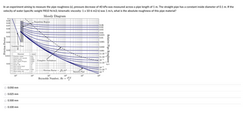
In an experiment aiming to measure the pipe roughness (ε), a pressure decrease of 40 kPa was measured across a pipe length of 1 m. The straight pipe has a constant inside diameter of 0.1 m. If the velocity of water (specific weight 9810 N/m³; kinematic viscosity: 1 x 10⁻⁶ m²/s) was 1 m/s, what is the absolute roughness of this pipe material?
**Diagram Explanation:**
The **Moody Diagram** included in the image is used to determine the friction factor in pipes for different flow conditions.
- **Axes:**
- The horizontal axis represents the Reynolds Number (Re), ranging from 10³ to 10⁸.
- The vertical axis on the left is the Friction Factor, ranging from 0.01 to 0.1.
- The vertical axis on the right is the Relative Pipe Roughness (ε/d), ranging from 5 x 10⁻⁶ to 0.05.
- **Curves:**
- The curves on the diagram show the relationship between the Friction Factor and the Reynolds Number for different values of Relative Pipe Roughness.
- The chart distinguishes between different flow regimes: Laminar Flow, Transition Region, and Complete Turbulence.
- **Materials Section:**
- A table lists materials and their typical absolute roughness values (ε) in millimeters (mm):
- Concrete, cast cement: 0.5 mm
- Concrete, new smooth: 0.25 mm
- Drawn Tubing: 0.0015 mm
- Glass, Plastic Pipe: 0 mm
- Steel, rusted: 0.15 mm
- Steel, rusted old: 3 mm
- Steel, encrusted with limestone: 1.5 mm
- Steel, rusted or forged: 0.45 mm
- Water mains, old: 3 mm
**Answer Options (Multiple Choice):**
- ○ 0.050 mm
- ○ 0.025 mm
- ○ 0.500 mm
- ○ 0.100 mm
The reader is expected to use the information provided in the problem statement and the Moody Diagram to calculate the absolute roughness of the pipe material.
Expert Solution
This question has been solved!
Explore an expertly crafted, step-by-step solution for a thorough understanding of key concepts.
This is a popular solution
Trending nowThis is a popular solution!
Step by stepSolved in 3 steps with 1 images

Knowledge Booster
Learn more about
Need a deep-dive on the concept behind this application? Look no further. Learn more about this topic, civil-engineering and related others by exploring similar questions and additional content below.Similar questions
- Could I please get a full written solution on how to answer question 6 for this past paper question please?arrow_forwardHi, I need help with this question please. Thank you. A cantilever thin-walled cylindrical tube of inner diameter ? = 30cm and thickness ? = 1cm is subjected to a torque T and internal pressure p as shown below. The free end of the tube is closed. Strain gauges A and B mounted on the surface of the cylinder give readings ?? = 7.5 × 10^−6 and ?b = 19.7x10^−6, respectively. The bar is made of steel having Young's modulus E=200 GPa and Poisson's ration ? = 0.3. a) Determine the torque, T, and internal pressure, p. b) Determine the absolute maximum shear strain ???? at point C.arrow_forward
Recommended textbooks for you

 Structural Analysis (10th Edition)Civil EngineeringISBN:9780134610672Author:Russell C. HibbelerPublisher:PEARSON
 Principles of Foundation Engineering (MindTap Cou...Civil EngineeringISBN:9781337705028Author:Braja M. Das, Nagaratnam SivakuganPublisher:Cengage Learning
 Fundamentals of Structural AnalysisCivil EngineeringISBN:9780073398006Author:Kenneth M. Leet Emeritus, Chia-Ming Uang, Joel LanningPublisher:McGraw-Hill Education
 Traffic and Highway EngineeringCivil EngineeringISBN:9781305156241Author:Garber, Nicholas J.Publisher:Cengage Learning


Structural Analysis (10th Edition)
Civil Engineering
ISBN:9780134610672
Author:Russell C. Hibbeler
Publisher:PEARSON

Principles of Foundation Engineering (MindTap Cou...
Civil Engineering
ISBN:9781337705028
Author:Braja M. Das, Nagaratnam Sivakugan
Publisher:Cengage Learning

Fundamentals of Structural Analysis
Civil Engineering
ISBN:9780073398006
Author:Kenneth M. Leet Emeritus, Chia-Ming Uang, Joel Lanning
Publisher:McGraw-Hill Education


Traffic and Highway Engineering
Civil Engineering
ISBN:9781305156241
Author:Garber, Nicholas J.
Publisher:Cengage Learning