Introductory Circuit Analysis (13th Edition)
13th Edition
ISBN: 9780133923605
Author: Robert L. Boylestad
Publisher: PEARSON
expand_more
expand_more
format_list_bulleted
Concept explainers
Question

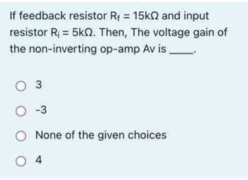
Transcribed Image Text:If feedback resistor R₁ = 15k and input
resistor R₁ = 5k. Then, The voltage gain of
the non-inverting op-amp Av is
O 3
O-3
None of the given choices
04
Expert Solution
This question has been solved!
Explore an expertly crafted, step-by-step solution for a thorough understanding of key concepts.
Step by stepSolved in 2 steps with 2 images

Knowledge Booster
Learn more about
Need a deep-dive on the concept behind this application? Look no further. Learn more about this topic, electrical-engineering and related others by exploring similar questions and additional content below.Similar questions
- The longer a signal is applied to the input of an integrator op amp, the output becomes. smaller O larger thearrow_forward4. Design a clipper circuit which limits input signals to +3V and -2V. This means that the output signal should not rise above 3V and should not fall below -2V. Assume Vs has amplitude of 5V and a frequency of 1 kHz, Verify your design by computer simulation on a computer.arrow_forwardDesign the following inverting amplifiers in Simulink and analyze the outputs. Get output with three different gains. Change values of resistors R1 and R2 to adjust gain. Take screenshots of all three outputs.arrow_forward
- Determine the voltage input to the inverting terminal of an op amp when 40 uvolts is applied to the noninverting terminal and the output through an open-loop gain of 150,000 is 15 volts. I need to show all workarrow_forwardThe components in the circuit shown below are ideal. If the op-amp is in positive feedback and the input voltage V, is a sine wave of amplitude 1 V, the output voltage V, is 1 kΩ ww +5 V 1 V 1 k2 V,o WW -1 V -5 V (a) a square wave of 5 V amplitude (b) an inverted sine wave of 1 V amplitude (c) a non-inverted sine wave of 2 V amplitude (d) a constant of either +5 or -5 Varrow_forwardPlease answer in typing format solution please only typing Please I will like it Thanks sirarrow_forward
arrow_back_ios
arrow_forward_ios
Recommended textbooks for you
 Introductory Circuit Analysis (13th Edition)Electrical EngineeringISBN:9780133923605Author:Robert L. BoylestadPublisher:PEARSON
 Delmar's Standard Textbook Of ElectricityElectrical EngineeringISBN:9781337900348Author:Stephen L. HermanPublisher:Cengage Learning
 Programmable Logic ControllersElectrical EngineeringISBN:9780073373843Author:Frank D. PetruzellaPublisher:McGraw-Hill Education
 Fundamentals of Electric CircuitsElectrical EngineeringISBN:9780078028229Author:Charles K Alexander, Matthew SadikuPublisher:McGraw-Hill Education
 Electric Circuits. (11th Edition)Electrical EngineeringISBN:9780134746968Author:James W. Nilsson, Susan RiedelPublisher:PEARSON
 Engineering ElectromagneticsElectrical EngineeringISBN:9780078028151Author:Hayt, William H. (william Hart), Jr, BUCK, John A.Publisher:Mcgraw-hill Education,

Introductory Circuit Analysis (13th Edition)
Electrical Engineering
ISBN:9780133923605
Author:Robert L. Boylestad
Publisher:PEARSON

Delmar's Standard Textbook Of Electricity
Electrical Engineering
ISBN:9781337900348
Author:Stephen L. Herman
Publisher:Cengage Learning

Programmable Logic Controllers
Electrical Engineering
ISBN:9780073373843
Author:Frank D. Petruzella
Publisher:McGraw-Hill Education

Fundamentals of Electric Circuits
Electrical Engineering
ISBN:9780078028229
Author:Charles K Alexander, Matthew Sadiku
Publisher:McGraw-Hill Education

Electric Circuits. (11th Edition)
Electrical Engineering
ISBN:9780134746968
Author:James W. Nilsson, Susan Riedel
Publisher:PEARSON

Engineering Electromagnetics
Electrical Engineering
ISBN:9780078028151
Author:Hayt, William H. (william Hart), Jr, BUCK, John A.
Publisher:Mcgraw-hill Education,