I+ Iェ-I,=0 R= 33052 生っ Lett: 6.98- luw I, -(00I; = 0 -(2) I. I, I3 Right : 15-330I2- lWT,=0 6.98V 15V (3) Vanls
I+ Iェ-I,=0 R= 33052 生っ Lett: 6.98- luw I, -(00I; = 0 -(2) I. I, I3 Right : 15-330I2- lWT,=0 6.98V 15V (3) Vanls

Introductory Circuit Analysis (13th Edition)
13th Edition
ISBN:9780133923605
Author:Robert L. Boylestad
Publisher:Robert L. Boylestad
Chapter1: Introduction
Section: Chapter Questions
Problem 1P: Visit your local library (at school or home) and describe the extent to which it provides literature...

Related questions
Question
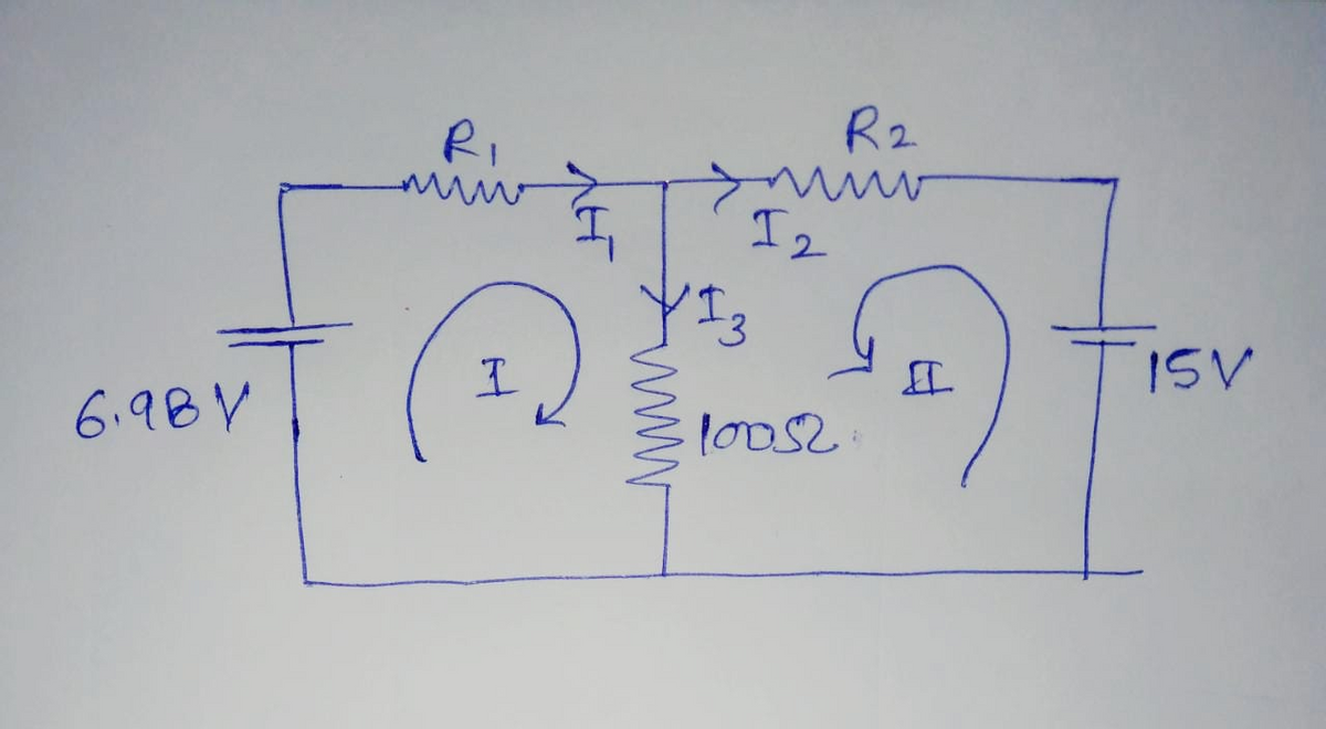
Hello I need help solving this for the left and right side of this circuit. I have also provided a picture for reference.

Transcribed Image Text:wsbek
C Conclusins
Page is
aya
An a tup Procedure K Analy KCan 4 s
DE Cent
ery o et enr Chec a rced DC Setup DC Setue
nesnter Check
Theary
cal Setp
Signal Generater
13
Vo
• Run #1
Run 1 Current Probe, Ch A (A)
Mean
DC Current Procedure:
Volts Out, Ch 01
a50 Output 1
1. Cick open the Signal Generator at the left of the screen Set 850 Output
1 for a DC Waveform and a DC Voltage of 15 ck the Auto button
6.98V -3.63x10⁻⁴A
Wefem DC
2. Cick Record (bottom left of screen
12
Vc
3. Wat several seconds until the measured current stops varying as the
average becomes well defined. Cick Stop.
4. Enter the votage and current values in Table ill
TOfet and Limi
V Run
1
Vot. Ch C
X Run 1 Q cal
wege im
0.00V
-.-mA
CurrentLmt1A
Auto
Ths de
T Aened an ina drent page etu he pege to
TN M he ege tab step buten Tu may
4farent page Retu the e t
Va
cenfigure th tel en th paar for later use
Volt. Ch B
HRun #1 a cal
0.00V
-.-mA
850 Output 2
50 Output 3
Table III: DC Circuit Voltages & Currants
13
(mA)
VA
12
Vo
(V)
(mA)
(mA)
(V)
1
2
Note: Athough the total current, 13, is meas ured directly, 11 and 12 are cak ulated from the measured votage drops using AV/R-I. Although it
would be nice to meas ure them directly, shfting the ammeter ground introduces error of a few mA which decreases the precision of the
ex periment since the current values are qute small This realy is not a limitation on the res ults since this is what the ammeter does as wel. It
measures the voltage drop across a 0.1 0 precision resistor. We have just made our own ammeters by replacing the 0.10 resistor with the
known values for the resistors in the circut
Contrul
00:04.38
wtage Senser. ChA se ce w:
Raced Ca d
edy
Delet Lau
Condine
MMAM
I,+I2-I,=0 -
R= 33052
Let: 6-98- lw I, - l0 I; = 0 -(2)
I,
I
Right :
15-330I2 - loT, =0
6.98 v
I3
15V
(3)
Expert Solution
Step 1
The giving circuit diagram is shown below,

Step by step
Solved in 5 steps with 1 images

Knowledge Booster


Learn more about
Need a deep-dive on the concept behind this application? Look no further. Learn more about this topic, electrical-engineering and related others by exploring similar questions and additional content below.Recommended textbooks for you
Introductory Circuit Analysis (13th Edition)
Electrical Engineering
ISBN:
9780133923605
Author:
Robert L. Boylestad
Publisher:
PEARSON

Delmar's Standard Textbook Of Electricity
Electrical Engineering
ISBN:
9781337900348
Author:
Stephen L. Herman
Publisher:
Cengage Learning

Programmable Logic Controllers
Electrical Engineering
ISBN:
9780073373843
Author:
Frank D. Petruzella
Publisher:
McGraw-Hill Education
Introductory Circuit Analysis (13th Edition)
Electrical Engineering
ISBN:
9780133923605
Author:
Robert L. Boylestad
Publisher:
PEARSON
Delmar's Standard Textbook Of Electricity
Electrical Engineering
ISBN:
9781337900348
Author:
Stephen L. Herman
Publisher:
Cengage Learning
Programmable Logic Controllers
Electrical Engineering
ISBN:
9780073373843
Author:
Frank D. Petruzella
Publisher:
McGraw-Hill Education

Fundamentals of Electric Circuits
Electrical Engineering
ISBN:
9780078028229
Author:
Charles K Alexander, Matthew Sadiku
Publisher:
McGraw-Hill Education

Electric Circuits. (11th Edition)
Electrical Engineering
ISBN:
9780134746968
Author:
James W. Nilsson, Susan Riedel
Publisher:
PEARSON

Engineering Electromagnetics
Electrical Engineering
ISBN:
9780078028151
Author:
Hayt, William H. (william Hart), Jr, BUCK, John A.
Publisher:
Mcgraw-hill Education,