Introductory Circuit Analysis (13th Edition)
13th Edition
ISBN: 9780133923605
Author: Robert L. Boylestad
Publisher: PEARSON
expand_more
expand_more
format_list_bulleted
Question

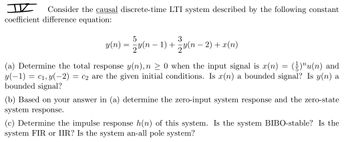
Transcribed Image Text:I Consider the causal discrete-time LTI system described by the following constant
coefficient difference equation:
5
3
y(n) = − y(n − 1) + − y(n − 2) + x(n)
(a) Determine the total response y(n), n ≥ 0 when the input signal is x(n) = (²)"u(n) and
y(−1) = c₁, y(−2) = c2 are the given initial conditions. Is x(n) a bounded signal? Is y(n) a
bounded signal?
(b) Based on your answer in (a) determine the zero-input system response and the zero-state
system response.
(c) Determine the impulse response h(n) of this system. Is the system BIBO-stable? Is the
system FIR or IIR? Is the system an-all pole system?
Expert Solution
This question has been solved!
Explore an expertly crafted, step-by-step solution for a thorough understanding of key concepts.
This is a popular solution
Trending nowThis is a popular solution!
Step by stepSolved in 3 steps with 4 images

Knowledge Booster
Learn more about
Need a deep-dive on the concept behind this application? Look no further. Learn more about this topic, electrical-engineering and related others by exploring similar questions and additional content below.Similar questions
- Choose the true option please..as fast as possible pleasearrow_forwardConsider a discrete-time LTI system with the input signal and impulse response: X(n) h(n) 3. -2 -1 10 2. -1 a) Write the mathematical equation of x{n] and h[n b) Calculate y[n] = x[n] * h[n], show all needed calculation steps. c) Plot y[n], label all parts of your plot. d) Explain in your words the technique and steps you have used to calculate y[n].arrow_forwardFor the following transfer function, if a PID controller is implemented, Check image for G(s) ; a) Draw a block diagram of the system.b) Find the closed-loop transfer function of the system. Leave the gain terms as K, Kp, Ki.c) Consider the gain values as Kp=2 and Ki=5 and Kd=10 and calculate the following. Please Clear ans.arrow_forward
- 1. Using iterative solution, find the first four output signal sample values for the following linear differ- ence equation: y[n] + 2y[n − 1] = x[n], with initial condition y[−1] = 0.5 and causal input x[n] = nu[n].arrow_forwardBased on our experiment. To make an 8 bits magnitude comparator from two 4 bits magnitude comparator(74LS85), the connection of input A=B, A>B and AB input is connected to High; A=B and AB inputs are connected to ground or Low. A=B input is connected to ground or Low; A>B and AB and Aarrow_forwardQ2: Draw the output waveforms (S, X, and Y) for the below sequential circuit by assuming the propagation delays of all the components that are shown in below figure equal to zero second. cik Cik DQ5arrow_forwardProblem 4. Given the Linear Difference Equation y[n] = 0.5y[n–1]+2x[n–1] Determine the output sequence for each of the following inputs. In each case the final answer y[n] has to be a real signal (nothing complex): Q1: x[n] = 2 cos(0.5zn)u[n] ; Q2. x[n] = 2 cos (0.5zn) Q3: x[n] =2 cos (0.5zn)u[-n-1]arrow_forwardConsider the system shown in Figure (1). This is a PID control of a second-order plant G(s). For the disturbance input in the absence of the reference input, the closed-loop transfer function is given as below: Ca(s) S D (s) (s + 10) (s² + 4s + 16) Rewrite the transfer function of PID controller in following form: 1 Ge(s)= K₂ (1+: + Tas) Tis R(3) K(as+1)(bs+1) PID controller D(s) Figure (1) +3.68+9 Plant G(s) C(s)arrow_forwardQ2: Draw the output waveforms (S, X, and Y) for the below sequential circuit by assuming the propagation delays of all the components that are shown in below figure equal to zero second. cik Cik DQ5arrow_forwardFor the digital system shown in below: 1) Write down the difference equation that represents the system. 2) Find the transfer function of the system, i.e. H(Z) x(n) y(n) 0.75 0. 125 Delay one sample Delay one samplearrow_forward6 - Forward path transfer function is applied to the input of a negative unit feedback system given as below, and the overrun rate at the output of the system is given as% OS = 5.4%. K G(s) = s(s +1) In this case, what is the damping rate of the system? A) 0.63 B) 0.57 C) 0.61 D) 0.68 E) 0.55arrow_forward1. Consider an input x[n] and a unit impulse response h[n] of a discrete-time LTI system given by: h[n] = 38[n + 3] + 28[n+ 1] + 8[n] – 8[n – 1] + 28[n – 2] 101 2 3 Determine and plot the output signal y[n] = x[n] + h[n].arrow_forwardarrow_back_iosSEE MORE QUESTIONSarrow_forward_ios
Recommended textbooks for you
 Introductory Circuit Analysis (13th Edition)Electrical EngineeringISBN:9780133923605Author:Robert L. BoylestadPublisher:PEARSON
 Delmar's Standard Textbook Of ElectricityElectrical EngineeringISBN:9781337900348Author:Stephen L. HermanPublisher:Cengage Learning
 Programmable Logic ControllersElectrical EngineeringISBN:9780073373843Author:Frank D. PetruzellaPublisher:McGraw-Hill Education
 Fundamentals of Electric CircuitsElectrical EngineeringISBN:9780078028229Author:Charles K Alexander, Matthew SadikuPublisher:McGraw-Hill Education
 Electric Circuits. (11th Edition)Electrical EngineeringISBN:9780134746968Author:James W. Nilsson, Susan RiedelPublisher:PEARSON
 Engineering ElectromagneticsElectrical EngineeringISBN:9780078028151Author:Hayt, William H. (william Hart), Jr, BUCK, John A.Publisher:Mcgraw-hill Education,

Introductory Circuit Analysis (13th Edition)
Electrical Engineering
ISBN:9780133923605
Author:Robert L. Boylestad
Publisher:PEARSON

Delmar's Standard Textbook Of Electricity
Electrical Engineering
ISBN:9781337900348
Author:Stephen L. Herman
Publisher:Cengage Learning

Programmable Logic Controllers
Electrical Engineering
ISBN:9780073373843
Author:Frank D. Petruzella
Publisher:McGraw-Hill Education

Fundamentals of Electric Circuits
Electrical Engineering
ISBN:9780078028229
Author:Charles K Alexander, Matthew Sadiku
Publisher:McGraw-Hill Education

Electric Circuits. (11th Edition)
Electrical Engineering
ISBN:9780134746968
Author:James W. Nilsson, Susan Riedel
Publisher:PEARSON

Engineering Electromagnetics
Electrical Engineering
ISBN:9780078028151
Author:Hayt, William H. (william Hart), Jr, BUCK, John A.
Publisher:Mcgraw-hill Education,