
Elements Of Electromagnetics
7th Edition
ISBN: 9780190698614
Author: Sadiku, Matthew N. O.
Publisher: Oxford University Press
expand_more
expand_more
format_list_bulleted
Related questions
Question
Strain and Stress equilibrium problems
Please do create a free body diagram
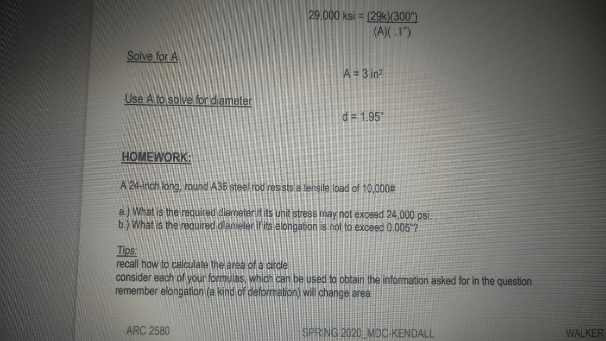

Transcribed Image Text:29,000 ksi = (29k)(300")
(A)( .1")
Solve for A
A = 3 in2
Use A to solve for diameter
d = 1.95"
HOMEWORK:
A 24-inch long. round A36 steel rod resists a tensile load of 10,000#
a.) What is the required diameterlif its unit stress may not exceed 24,000 psi.
b.) What is the required diameter if lits elongation is not to exceed 0.005"?
Tips:
recall how to calculate the area of a circle
consider each of your formulas, which can be used to obtain the information asked for in the question
remember elongation (a kind of deformation) will change area
ARC 2580
SPRING 2020 MDC-KENDALL
WALKER
Expert Solution
This question has been solved!
Explore an expertly crafted, step-by-step solution for a thorough understanding of key concepts.

This is a popular solution

Trending nowThis is a popular solution!

Step by stepSolved in 2 steps with 2 images

Knowledge Booster


Learn more about
Need a deep-dive on the concept behind this application? Look no further. Learn more about this topic, mechanical-engineering and related others by exploring similar questions and additional content below.Similar questions
- You are given a square rod of 6061-T6 aluminum (cross-section = 4mm X 4mm, length = 2.3m). The material has a Young’s modulus of 72 GPa. If a compressive load of 3 kN is applied parallel to the 2.3m dimension, what is the resulting engineering normal strain?arrow_forwardbehaviour of a material is shown in the figure. Its resilience in N-m/m³, are respectively . The stress-strain and toughness, Strain (MPa) (a) 28×104,76 × 104 (c) 14×104,90 × 104 150 120 90 70 30 0.004 0.008 0.012 Strain (mm/mm) (b) 28×104,48×104 (d) 76x104,104×104arrow_forwardProblem 4: In the Figure shown, the Q8 element has equally-spaced nodes. The nodes 1, 4, 6 of the Q8 element are collapsed into one node; and nodes 7 and 2 are moved towards the collapsed node at a distance equal to one fourth the length of the element sides 1-8 and 1-3 to form an F6 element, as shown below. model fracture mechanics problem with the crack tip placed at the collapsed node. The F6 element is used to 1) Derive x and y in terms of g and n for the Q8 element where & and n are coordinates of the master element. 2) Modify and derive x and y in terms of g and n for the F6 element. 3) Determine the variation of ɛxx and ɛyy along r. Check for singularity at the collapsed node. y y 7 (2,2) (0,2) 8 6 7 O 5 1,4,6 r 2 1 3 3 (0,0) (2,0) F6 Q8arrow_forward
- (Solid Mechanics) Explain how to construct the upper right corner (red boundary indicated below) of the envelope for the maximum shear stress criterion.arrow_forwardA man leg can be thought of as a shaft of bone 1.2 m long. If the strain is 1.3x10⁻⁴ when the leg supports his weight, by how much is his leg shortened?arrow_forward3arrow_forward
- Hi, I have been given this pin-jointed frame analysis to solve (see pictures of the structure attached). Can you help me answer all the questions below? Especially the one about the bending moment and shear force. The Figure 2 attached is a simplified structure to undertake a structural analysis on a concept design for a low cost stroller/buggy for children. The buggy consists of a number of metal sections that are pin-jointed together. The buggy is designed to accommodate a child of mass no more than 20 kg, sat on the seat which is supported at four points (Fc) on the frame of the buggy. Assume that the weight of the child is equally distributed across all of the points indicated on Figure 2 as Fc. Assume that there are no additional forces applied to the handle of the buggy, that the buggy is static (stationary) and that the buggy, and the elements of the frame have no mass. At points A and G, there are roll supports. At Points B, F and D there are the pin supports. I am required…arrow_forwardStress Strain Diagram The Data shown in the table have been obtained from a tensile test conducted on a high-strength steel. The test specimen had a diameter of 0.505 inch and a gage length of 2.00 inch. Using software. plot the Stress-Strain Diagram for this steel and determine its: A= TTdT(050s A %3D 1. Proportional Limit, 2. Modulus of Elasticity, 3. Yield Strength (SY) at 0.2% Offset, 4. Ultimate Strength (Su), 5. Percent Elongation in 2.00 inch, 6. Percent Reduction in Area, 7. Present the results (for Steps 1-6) in a highly organized table. e Altac ie sheet (as problelle 4 A = 0.2.002 BEOINNING of the effort Elongation (in) Elongation (In) Load Load #: #3 (Ib) (Ib) 1 0.0170 15 12,300 0.0004 1,500 16 12,200 0.0200 0.0010 3. 3,100 17 12,000 0.0275 0.0016 4,700 18 13,000 0.0335 5. 6,300 0.0022 19 15,000 0.0400 0.0026 6. 8,000 20 16,200 0.055 0.0032 9,500 21 17,500 0.0680 0.0035 8. 11,000 22 18,800 0.1080 0.0041 11,800 23 19,600 0.1515 0.0051 24 20,100 0.2010 10 12,300 0.0071 25…arrow_forwardThis is Mechanical Engineering. Please answer with clear work and answers. Thank youarrow_forward
- 100 mm must elongate only 5 mm when a tensle load of 100,000 N is applied. Under these A cylindrical specimen of a brass alloy having a circumstances what must be the radius of the specimen? Consider this brass alloy to have the stress-strain behavior shown in Figure below. Tensile strengh 450 MPa (65,000 p A00 10 pu 300 200- 30 Yield strength 250 MPa (36,000 psi 2아 100 1아 100 0.005 0.20 0.30 0.40arrow_forwardName the 7 different points on a stress-strain diagram?arrow_forward45-degree rosette *Please answer this analytically!*arrow_forward
arrow_back_ios
SEE MORE QUESTIONS
arrow_forward_ios
Recommended textbooks for you
- Elements Of ElectromagneticsMechanical EngineeringISBN:9780190698614Author:Sadiku, Matthew N. O.Publisher:Oxford University Press
 Mechanics of Materials (10th Edition)Mechanical EngineeringISBN:9780134319650Author:Russell C. HibbelerPublisher:PEARSON
 Thermodynamics: An Engineering ApproachMechanical EngineeringISBN:9781259822674Author:Yunus A. Cengel Dr., Michael A. BolesPublisher:McGraw-Hill Education
  Control Systems EngineeringMechanical EngineeringISBN:9781118170519Author:Norman S. NisePublisher:WILEY
 Mechanics of Materials (MindTap Course List)Mechanical EngineeringISBN:9781337093347Author:Barry J. Goodno, James M. GerePublisher:Cengage Learning
 Engineering Mechanics: StaticsMechanical EngineeringISBN:9781118807330Author:James L. Meriam, L. G. Kraige, J. N. BoltonPublisher:WILEY
Elements Of Electromagnetics
Mechanical Engineering
ISBN:9780190698614
Author:Sadiku, Matthew N. O.
Publisher:Oxford University Press
Mechanics of Materials (10th Edition)
Mechanical Engineering
ISBN:9780134319650
Author:Russell C. Hibbeler
Publisher:PEARSON
Thermodynamics: An Engineering Approach
Mechanical Engineering
ISBN:9781259822674
Author:Yunus A. Cengel Dr., Michael A. Boles
Publisher:McGraw-Hill Education
Control Systems Engineering
Mechanical Engineering
ISBN:9781118170519
Author:Norman S. Nise
Publisher:WILEY
Mechanics of Materials (MindTap Course List)
Mechanical Engineering
ISBN:9781337093347
Author:Barry J. Goodno, James M. Gere
Publisher:Cengage Learning
Engineering Mechanics: Statics
Mechanical Engineering
ISBN:9781118807330
Author:James L. Meriam, L. G. Kraige, J. N. Bolton
Publisher:WILEY