Elements Of Electromagnetics
7th Edition
ISBN: 9780190698614
Author: Sadiku, Matthew N. O.
Publisher: Oxford University Press
expand_more
expand_more
format_list_bulleted
Concept explainers
Question

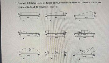
Transcribed Image Text:For given distributed loads, see figures below and determine resultant forces and moments around load ends (points A and B). Assume \( p = 2 \, \text{kN/m} \).
### Diagram Descriptions:
**a)**
- A beam (4 m) under a uniform load of \( 2p \) at both ends (A and B).
**b)**
- A beam (4 m) with a linearly increasing load from \( p \) at A to \( 3p \) at B.
**c)**
- A beam (10 m) with a linearly increasing load from 0 at A to \( 3p \) at B.
**d)**
- A beam (6 m) under a triangular load, decreasing from \( 2p \) at A to zero at a point 3 m along the beam and then increasing back to \( 2p \) at B.
**e)**
- A beam (12 m) with two concentrated loads of \( 2p \) positioned 8 m from A and at B.
**f)**
- A beam (6 m) with two rectangular loads of \( 2p \) each, first 2 m long at A, and second 2 m long with a gap between them.
**g)**
- A beam (20 m) with a parabolic load distribution peaking at the center with a magnitude of \( 2p \).
**h)**
- A beam (7 m) with a uniform downward load of \( 2p \) across the entire length.
**i)**
- A beam (12 m) with a trapezoidal load starting from \( 1.5p \) at A and increasing to \( 5p \) at B.
Each diagram represents different loading conditions, which must be analyzed to find the resulting forces and moments at points A and B.

Transcribed Image Text:3. Using the solution developed above, redo all 9 load distributions, and use those solutions to check your work in problem #1.
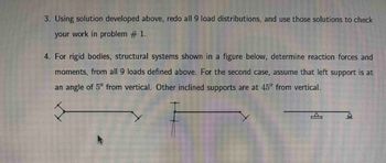
4. For rigid bodies, structural systems shown in the figure below, determine reaction forces and moments from all 9 loads defined above. For the second case, assume that the left support is at an angle of 5° from vertical. Other inclined supports are at 45° from vertical.
**Diagrams:**
- **First Diagram:** A horizontal beam with supports angled outward at both ends.
- **Second Diagram:** A horizontal beam with a vertical support descending downwards from the left endpoint and an angled support at the right endpoint.
- **Third Diagram:** A horizontal beam with simple triangular supports placed underneath both ends.
These configurations are used to determine reaction forces and moments for given structural loads.
Expert Solution
This question has been solved!
Explore an expertly crafted, step-by-step solution for a thorough understanding of key concepts.
This is a popular solution
Trending nowThis is a popular solution!
Step by stepSolved in 6 steps with 6 images

Follow-up Questions
Read through expert solutions to related follow-up questions below.
Follow-up Question
Hi could you also please give the solution to d, e, f, g, h, i? I am stuck on those right now.
Solution
by Bartleby Expert
Follow-up Questions
Read through expert solutions to related follow-up questions below.
Follow-up Question
Hi could you also please give the solution to d, e, f, g, h, i? I am stuck on those right now.
Solution
by Bartleby Expert
Knowledge Booster
Learn more about
Need a deep-dive on the concept behind this application? Look no further. Learn more about this topic, mechanical-engineering and related others by exploring similar questions and additional content below.Similar questions
- i need the answer quicklyarrow_forwardA simply supported shaft arrangement is shown in the figure. A solid shaft of 50 mm diameter made of low-carbon steel is used. Given values are: X;=762 mm X:=1016 mm X3=508 mm PA=356 N Ps=534 N Solution: Determine first critical speeds: a) 1155 rpm b) 648 грm a) Unloaded shaft b) Rayleigh method с) 651 грm c) Dunkerley methodarrow_forwardPlease answer all thank you(6)arrow_forward
Recommended textbooks for you
 Elements Of ElectromagneticsMechanical EngineeringISBN:9780190698614Author:Sadiku, Matthew N. O.Publisher:Oxford University Press
 Mechanics of Materials (10th Edition)Mechanical EngineeringISBN:9780134319650Author:Russell C. HibbelerPublisher:PEARSON
 Thermodynamics: An Engineering ApproachMechanical EngineeringISBN:9781259822674Author:Yunus A. Cengel Dr., Michael A. BolesPublisher:McGraw-Hill Education
 Control Systems EngineeringMechanical EngineeringISBN:9781118170519Author:Norman S. NisePublisher:WILEY
 Mechanics of Materials (MindTap Course List)Mechanical EngineeringISBN:9781337093347Author:Barry J. Goodno, James M. GerePublisher:Cengage Learning
 Engineering Mechanics: StaticsMechanical EngineeringISBN:9781118807330Author:James L. Meriam, L. G. Kraige, J. N. BoltonPublisher:WILEY

Elements Of Electromagnetics
Mechanical Engineering
ISBN:9780190698614
Author:Sadiku, Matthew N. O.
Publisher:Oxford University Press

Mechanics of Materials (10th Edition)
Mechanical Engineering
ISBN:9780134319650
Author:Russell C. Hibbeler
Publisher:PEARSON

Thermodynamics: An Engineering Approach
Mechanical Engineering
ISBN:9781259822674
Author:Yunus A. Cengel Dr., Michael A. Boles
Publisher:McGraw-Hill Education

Control Systems Engineering
Mechanical Engineering
ISBN:9781118170519
Author:Norman S. Nise
Publisher:WILEY

Mechanics of Materials (MindTap Course List)
Mechanical Engineering
ISBN:9781337093347
Author:Barry J. Goodno, James M. Gere
Publisher:Cengage Learning

Engineering Mechanics: Statics
Mechanical Engineering
ISBN:9781118807330
Author:James L. Meriam, L. G. Kraige, J. N. Bolton
Publisher:WILEY