Introductory Circuit Analysis (13th Edition)
13th Edition
ISBN: 9780133923605
Author: Robert L. Boylestad
Publisher: PEARSON
expand_more
expand_more
format_list_bulleted
Question
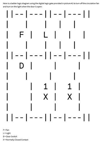
Can someone hand draw a ladder logic in the picture provided below. im not used to seeing this type of ladder logic.

Transcribed Image Text:Here is a ladder logic diagram using the digital logic gate provided in picture #1 to turn off the circulation fan
and turn on the light when the door is open:
||
·||
- 1
L
FI
|
|--|
|
—
- -
DI
|
|| - - | -
-
F = Fan
L = Light
D = Door Switch
X = Normally Closed Contact
|| |-- |
|
I I
|
| | |
-||-- |·
|
|
1 |
X I
|
|
-||
|
1 |
X I
-- ||-- |-- - ||
Expert Solution
This question has been solved!
Explore an expertly crafted, step-by-step solution for a thorough understanding of key concepts.
This is a popular solution
Trending nowThis is a popular solution!
Step by stepSolved in 3 steps with 3 images

Knowledge Booster
Learn more about
Need a deep-dive on the concept behind this application? Look no further. Learn more about this topic, electrical-engineering and related others by exploring similar questions and additional content below.Similar questions
- Draw the AND and OR gate logic diagram of the expression. X=[[K(K+L) +M] Logic diagram using AND-OR gates Redraw the circuit using positive NOR gates. Logic diagram using positive NOR gatesarrow_forwardLabel all outputs and compule the truth table for the follewing logic aircuit: Aarrow_forwardPLease Explain the design process of this thoroughlyarrow_forward
- Conclusion From your life experiences, list 3-5 examples of products that you have used that contain combinational logic. Throughout this activity we used switches for the circuit inputs and a probe for the circuit outputs. Though this works fine for testing purposes, it is not practical for real-world applications of combinational logic circuits. List three input and three output devices that would be used with real world applications of combinational logic. Going Further – Optional As mentioned in the purpose section of this activity, combinational logic circuits can be implemented with a variety of different logic gates. One such gate is called the NAND gates (see below). Functionally, the NAND gate is an AND gate with its output inverted. The picture added goes here Using what you know about the AND gate and Inverter gates, complete the truth table for the NAND gate. A B C 0 0 0 1 1 0 1 1…arrow_forward14. Identify each logic gate shown on the given diagrams * E Your answerarrow_forward
arrow_back_ios
arrow_forward_ios
Recommended textbooks for you
 Introductory Circuit Analysis (13th Edition)Electrical EngineeringISBN:9780133923605Author:Robert L. BoylestadPublisher:PEARSON
 Delmar's Standard Textbook Of ElectricityElectrical EngineeringISBN:9781337900348Author:Stephen L. HermanPublisher:Cengage Learning
 Programmable Logic ControllersElectrical EngineeringISBN:9780073373843Author:Frank D. PetruzellaPublisher:McGraw-Hill Education
 Fundamentals of Electric CircuitsElectrical EngineeringISBN:9780078028229Author:Charles K Alexander, Matthew SadikuPublisher:McGraw-Hill Education
 Electric Circuits. (11th Edition)Electrical EngineeringISBN:9780134746968Author:James W. Nilsson, Susan RiedelPublisher:PEARSON
 Engineering ElectromagneticsElectrical EngineeringISBN:9780078028151Author:Hayt, William H. (william Hart), Jr, BUCK, John A.Publisher:Mcgraw-hill Education,

Introductory Circuit Analysis (13th Edition)
Electrical Engineering
ISBN:9780133923605
Author:Robert L. Boylestad
Publisher:PEARSON

Delmar's Standard Textbook Of Electricity
Electrical Engineering
ISBN:9781337900348
Author:Stephen L. Herman
Publisher:Cengage Learning

Programmable Logic Controllers
Electrical Engineering
ISBN:9780073373843
Author:Frank D. Petruzella
Publisher:McGraw-Hill Education

Fundamentals of Electric Circuits
Electrical Engineering
ISBN:9780078028229
Author:Charles K Alexander, Matthew Sadiku
Publisher:McGraw-Hill Education

Electric Circuits. (11th Edition)
Electrical Engineering
ISBN:9780134746968
Author:James W. Nilsson, Susan Riedel
Publisher:PEARSON

Engineering Electromagnetics
Electrical Engineering
ISBN:9780078028151
Author:Hayt, William H. (william Hart), Jr, BUCK, John A.
Publisher:Mcgraw-hill Education,