Introductory Circuit Analysis (13th Edition)
13th Edition
ISBN: 9780133923605
Author: Robert L. Boylestad
Publisher: PEARSON
expand_more
expand_more
format_list_bulleted
Concept explainers
Question
Use the following values:
Vs=6
R1=7
R2=7

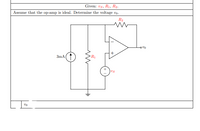
Transcribed Image Text:Given: vs, R1, R2.
Assume that the op-amp is ideal. Determine the voltage vo.
R2
3mA
R1
Us
Expert Solution
This question has been solved!
Explore an expertly crafted, step-by-step solution for a thorough understanding of key concepts.
This is a popular solution
Trending nowThis is a popular solution!
Step by stepSolved in 2 steps with 2 images

Knowledge Booster
Learn more about
Need a deep-dive on the concept behind this application? Look no further. Learn more about this topic, electrical-engineering and related others by exploring similar questions and additional content below.Similar questions
- Please I need the exact number that goes to the box after expressing the answer to two significant figures.arrow_forwardProblem 4 a) PEFF R₁ AAA b) Vs 5 V wwwwww R₁ R₂3 Vout 3.3 V Voltage generated by pins of Arduino microcontroller board is 5V. Voltages that can be applied to Raspberry Pi microcontroller boards cannot exceed 3.3 V, otherwise Raspberry Pi board will be permanently damaged. The so-called voltage level shifting is required. One of the ways how this can be achieved is by using the voltage divider circuit as shown in a), and schematically represented in b). Design this voltage divider circuit. Hint: in the voltage divider formula resistance of one of resistors can be chosen arbitrarily, so the other resistor value can be computed. In order not to exceed power ratings of resistors use resistor values not lower than 1 KQ.arrow_forward39. You and your lab partner have built the circuit shown in Figure 1.56. The three resistors, R1, R2 and R3 all have resistances of 1 k2, while the two voltage sources have 5 V and 3 V (as shown). The circuit has two output terminals, A and B. Answer the following questions about the circuit. (NOTE: The orientation of the voltage sources is important.) (a) What is the voltage drop across R1 R2 R3 A 5 V 3 V B Figure 1.56: The circuit for problem 39. R3? (b) What is the current flowing through R1? (c) Sketch the Thévenin equivalent circuit as seen looking into the terminals A and B. What is the Thévenin voltage, Vth, of the circuit? (d) What is the power supplied by the two voltage sources? (e) In order to safely determine the Thévenin resistance of your circuit, you connect a fourth resistor, R4 = 1 k2, between A and B. Using your trusty yellow DVM, you measure a potential difference across R4 to be 0.4 V. Using %3Darrow_forward
- solution plsarrow_forwardASSUME ARBITRARY VALUES FOR ALL OR PLUG IN VALUES U CAN USE AS AN EXAMPLE. A Zener diode with an arbitrary Zener voltage is used to build the circuit below. Calculate:(a) The current I_z(b) The voltage V_out(c) The power absorbed by the Zener diodearrow_forward1.32 In the circuit of Figure P1.32, assume v2=vs/6 and the power delivered by the source is 150 mW. Also assume that Ry - 8 ko, R2 = 10 ko, R3 = 12 ko Find R, Vs ,V2, and = i. (Hint: Apply KVL around the circuit, using Ohm's law to express the voltage drop across each resistance.) Please answer in typing formatarrow_forward
arrow_back_ios
arrow_forward_ios
Recommended textbooks for you
 Introductory Circuit Analysis (13th Edition)Electrical EngineeringISBN:9780133923605Author:Robert L. BoylestadPublisher:PEARSON
 Delmar's Standard Textbook Of ElectricityElectrical EngineeringISBN:9781337900348Author:Stephen L. HermanPublisher:Cengage Learning
 Programmable Logic ControllersElectrical EngineeringISBN:9780073373843Author:Frank D. PetruzellaPublisher:McGraw-Hill Education
 Fundamentals of Electric CircuitsElectrical EngineeringISBN:9780078028229Author:Charles K Alexander, Matthew SadikuPublisher:McGraw-Hill Education
 Electric Circuits. (11th Edition)Electrical EngineeringISBN:9780134746968Author:James W. Nilsson, Susan RiedelPublisher:PEARSON
 Engineering ElectromagneticsElectrical EngineeringISBN:9780078028151Author:Hayt, William H. (william Hart), Jr, BUCK, John A.Publisher:Mcgraw-hill Education,

Introductory Circuit Analysis (13th Edition)
Electrical Engineering
ISBN:9780133923605
Author:Robert L. Boylestad
Publisher:PEARSON

Delmar's Standard Textbook Of Electricity
Electrical Engineering
ISBN:9781337900348
Author:Stephen L. Herman
Publisher:Cengage Learning

Programmable Logic Controllers
Electrical Engineering
ISBN:9780073373843
Author:Frank D. Petruzella
Publisher:McGraw-Hill Education

Fundamentals of Electric Circuits
Electrical Engineering
ISBN:9780078028229
Author:Charles K Alexander, Matthew Sadiku
Publisher:McGraw-Hill Education

Electric Circuits. (11th Edition)
Electrical Engineering
ISBN:9780134746968
Author:James W. Nilsson, Susan Riedel
Publisher:PEARSON

Engineering Electromagnetics
Electrical Engineering
ISBN:9780078028151
Author:Hayt, William H. (william Hart), Jr, BUCK, John A.
Publisher:Mcgraw-hill Education,