Database System Concepts
7th Edition
ISBN: 9780078022159
Author: Abraham Silberschatz Professor, Henry F. Korth, S. Sudarshan
Publisher: McGraw-Hill Education
expand_more
expand_more
format_list_bulleted
Question

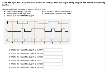
Transcribed Image Text:Given the input for a negative level clocked D Flip-flop, draw the output timing diagram and answer the following
questions.
Assume that initially, the value of output is 0 (zero). Write:
A - if the output is a high logic level
B - if the output is a low logic level
C - if there is an indeterminate output
CLK
D
с
D - if the output transitions from 0 to 1
E - if the output transitions from 1 to 0
1. What is the value of the output at point A?
2. What is the value of the output at point B?
3. What is the value of the output at point C?
4. What is the value of the output at point D?
5. What is the value of the output at point E?
6. What is the value of the output at point F?
D
E
F
Expert Solution
This question has been solved!
Explore an expertly crafted, step-by-step solution for a thorough understanding of key concepts.
This is a popular solution
Trending nowThis is a popular solution!
Step by stepSolved in 3 steps with 1 images

Knowledge Booster
Learn more about
Need a deep-dive on the concept behind this application? Look no further. Learn more about this topic, computer-science and related others by exploring similar questions and additional content below.Similar questions
- The boolean expression for the below logic circuit is equivalent to В C Aarrow_forwardFor the following logic circuit: A B F C 1- Write the logic expression for the output 2- 3- Write the truth table implement the above circuit (using Nand gates only)arrow_forward1. Identify each of these logic gates by name, and complete their respective truth tables Output Output Output B AB Output AB Output AB Output 10 A Output Output A Output AB Output A Output A Output Output Output Output 13 13 AB Outpt ABOutput AB Output 10arrow_forward
- 2. Design a logic circuit with two inputs and 4 outputs, with each of the outputs hooked up to an LED. Only the first LED should light up when the input values are 00. Only the next LED should light up with the input values are 01. Only the following LED should light up for 10, and only the last LED should light up for input 11. Thus for each input combination, you should have one LED only being lit. This is called a DECODER circuit, you are decoding 2 bit binary input to one of 4 discrete outputs. a. Create the truth table (use the standard truth table format). b. Write a Boolean expression that corresponds to the truth table.arrow_forwardDesign a modulo-6 counter, which counts in the sequence 0, 1, 2, 3, 4, 5, 0, 1, .... The counter counts the clock pulses if its enable input, w, is equal to 1. Use D flip-flops in your circuit. Repeat Problem 6.23 using JK flip-flops. Repeat Problem 6.23 using T flip-flops.arrow_forwardA combination of inverters is shown in Figure 3–77. If a HIGH is applied to point A, determine the logic levels at points B through F. B D A E Farrow_forward
- Q1/ Estimate the Truth Table of the logic circuit shown below and use it to draw the timing diagram of the output signal X and Y in proper relation to the inputs A :: Y сеarrow_forwardQ1: Can you answer this question with clearly showing your workarrow_forwardDesign an asynchronous sequential logic circuit which has inputs (X1 and X2) and one output (Z) the output (z) must go to (1) when at the end of the input sequence (00,10), This output must be maintained (unchanged) for all inputs change until the sequence (11,10) occurs, then the output must go to zero (0). and The output flips when the input is (01,10)arrow_forward
arrow_back_ios
arrow_forward_ios
Recommended textbooks for you
 Database System ConceptsComputer ScienceISBN:9780078022159Author:Abraham Silberschatz Professor, Henry F. Korth, S. SudarshanPublisher:McGraw-Hill Education
 Starting Out with Python (4th Edition)Computer ScienceISBN:9780134444321Author:Tony GaddisPublisher:PEARSON
 Digital Fundamentals (11th Edition)Computer ScienceISBN:9780132737968Author:Thomas L. FloydPublisher:PEARSON
 C How to Program (8th Edition)Computer ScienceISBN:9780133976892Author:Paul J. Deitel, Harvey DeitelPublisher:PEARSON
 Database Systems: Design, Implementation, & Manag...Computer ScienceISBN:9781337627900Author:Carlos Coronel, Steven MorrisPublisher:Cengage Learning
 Programmable Logic ControllersComputer ScienceISBN:9780073373843Author:Frank D. PetruzellaPublisher:McGraw-Hill Education

Database System Concepts
Computer Science
ISBN:9780078022159
Author:Abraham Silberschatz Professor, Henry F. Korth, S. Sudarshan
Publisher:McGraw-Hill Education

Starting Out with Python (4th Edition)
Computer Science
ISBN:9780134444321
Author:Tony Gaddis
Publisher:PEARSON

Digital Fundamentals (11th Edition)
Computer Science
ISBN:9780132737968
Author:Thomas L. Floyd
Publisher:PEARSON

C How to Program (8th Edition)
Computer Science
ISBN:9780133976892
Author:Paul J. Deitel, Harvey Deitel
Publisher:PEARSON

Database Systems: Design, Implementation, & Manag...
Computer Science
ISBN:9781337627900
Author:Carlos Coronel, Steven Morris
Publisher:Cengage Learning

Programmable Logic Controllers
Computer Science
ISBN:9780073373843
Author:Frank D. Petruzella
Publisher:McGraw-Hill Education