Introductory Circuit Analysis (13th Edition)
13th Edition
ISBN: 9780133923605
Author: Robert L. Boylestad
Publisher: PEARSON
expand_more
expand_more
format_list_bulleted
Question

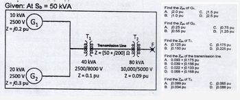
Transcribed Image Text:Given: At Sb= 50 kVA
10 KVA
2500 V G₁
Z=j0.2 pu
20 kVA
2500 V
Z-j0.3 pu
G₂
T₁
Transmission Line
Z=(50+1200) 2
40 KVA
2500/8000 V
Z = 0.1 pu
T₂
Leeke
80 kVA
10,000/5000 V
Z = 0.09 pu
Find the Zpu of G1.
A. j2.0 pu
B. j1.0 pu
Find the Zpu of G2.
A. j0.25 pu
B. j0.55 pu
Find the Zpu of T₁.
A. j0.125 pu
B. j0.150 pu
C. 0.022+ j0.133 pu
D. 0.068 + j0.168 pu
C.
D.
Find the Zpu of T2.
A. j0.099 pu
B. j0.034 pu
j1.5 pu
j2.5 pu
C. j0.75 pu
D. j1.25 pu
Find the Zpu of the transmission line.
A. 0.093+j0.175 pu
B. 0.039+ j0.156 pu
C. j0.175 pu
D. j0.225 pu
C. j0.065 pu
D. j0.088 pu
Expert Solution
This question has been solved!
Explore an expertly crafted, step-by-step solution for a thorough understanding of key concepts.
Step by stepSolved in 5 steps with 1 images

Knowledge Booster
Learn more about
Need a deep-dive on the concept behind this application? Look no further. Learn more about this topic, electrical-engineering and related others by exploring similar questions and additional content below.Similar questions
- Could you solve the question clearly ?arrow_forwardA Time left 0:51 Z1 22 V sine sine B Let Z1 = 3+j4 ohm and Z2 = 3-j4 ohm. Let the current source phasor be I = j10 ampere and V = 50 volt and phase angle 0 degree. Both sources operate at 50 Hz. Real part of the Thevenin Voltage phasor between nodes A and B is Volt Imaginary part of the Thevenin Voltage phasor between nodes A and B is Volt Real part of the Thevenin Impedance between nodes A and B is Ohmarrow_forwardNumber of output pins in IC74153. Options A-1 B-2 C-3 D-4arrow_forward
- Q1. (a) Considering pure inductance in an ac circuit element, show that the alternating current lags the voltage by 0.5. j4! b j40 a 100 L0° (V) N100 L 60° (V)arrow_forwardFind steady -state expression of current Io using mesh analysis. Answer is io = 2.532 cos (40000t+161.560^deg ) Aarrow_forward= = Impedances Z₂ and z3 in parallel are in series with an impedance z₁ across a 100V,50Hz AC supply. Z₁ (6.25 +j1.25)ohms, Z₂ = (5 + j0)ohms and Z3 (5 - jxc)ohms. Determine the value of capacitance Xc said that the total current of the circuit will be in phase with the total voltage. What is then the circuit current and power?arrow_forward
- The series capacitance causes real power loss in the conductor. Select one: O True O False gearrow_forwardSolve in detail to understandarrow_forward181% O uo 9:02 Asiacell I. docs.google.com a A charge of 15C flow in a conductor in .5 * :2min, then the current produced is 125A O 0.125A 12.5A 1.25A In figure below, The total voltage of the .3 sources connected in series is HHH- 6 V 6 V 8 V +20v +4v -20v -4v + -> 72arrow_forward
arrow_back_ios
arrow_forward_ios
Recommended textbooks for you
 Introductory Circuit Analysis (13th Edition)Electrical EngineeringISBN:9780133923605Author:Robert L. BoylestadPublisher:PEARSON
 Delmar's Standard Textbook Of ElectricityElectrical EngineeringISBN:9781337900348Author:Stephen L. HermanPublisher:Cengage Learning
 Programmable Logic ControllersElectrical EngineeringISBN:9780073373843Author:Frank D. PetruzellaPublisher:McGraw-Hill Education
 Fundamentals of Electric CircuitsElectrical EngineeringISBN:9780078028229Author:Charles K Alexander, Matthew SadikuPublisher:McGraw-Hill Education
 Electric Circuits. (11th Edition)Electrical EngineeringISBN:9780134746968Author:James W. Nilsson, Susan RiedelPublisher:PEARSON
 Engineering ElectromagneticsElectrical EngineeringISBN:9780078028151Author:Hayt, William H. (william Hart), Jr, BUCK, John A.Publisher:Mcgraw-hill Education,

Introductory Circuit Analysis (13th Edition)
Electrical Engineering
ISBN:9780133923605
Author:Robert L. Boylestad
Publisher:PEARSON

Delmar's Standard Textbook Of Electricity
Electrical Engineering
ISBN:9781337900348
Author:Stephen L. Herman
Publisher:Cengage Learning

Programmable Logic Controllers
Electrical Engineering
ISBN:9780073373843
Author:Frank D. Petruzella
Publisher:McGraw-Hill Education

Fundamentals of Electric Circuits
Electrical Engineering
ISBN:9780078028229
Author:Charles K Alexander, Matthew Sadiku
Publisher:McGraw-Hill Education

Electric Circuits. (11th Edition)
Electrical Engineering
ISBN:9780134746968
Author:James W. Nilsson, Susan Riedel
Publisher:PEARSON

Engineering Electromagnetics
Electrical Engineering
ISBN:9780078028151
Author:Hayt, William H. (william Hart), Jr, BUCK, John A.
Publisher:Mcgraw-hill Education,