
Introductory Circuit Analysis (13th Edition)
13th Edition
ISBN: 9780133923605
Author: Robert L. Boylestad
Publisher: PEARSON
expand_more
expand_more
format_list_bulleted
Related questions
Question
I need help with problem 10.77

Transcribed Image Text:**Figure P10.73** and **Figure P10.75**: These figures are not visible in the current image.
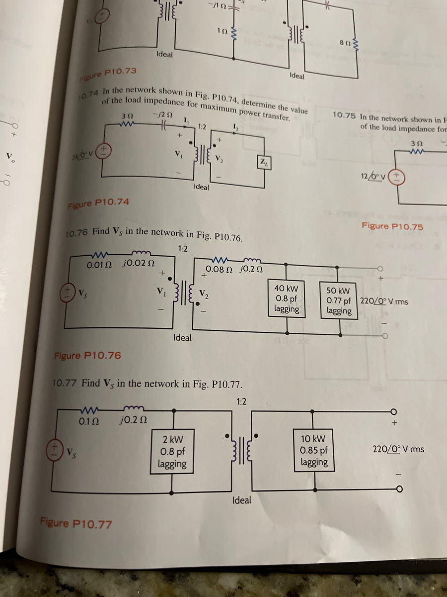
**Figure P10.74**:
- **Problem Statement 10.74**: Determine the value of the load impedance for maximum power transfer in the network shown.
- **Diagram Description**:
- A circuit with a voltage source \(10 \angle 0^\circ \, V\) and a series resistance of 3 \(\Omega\).
- The circuit includes an inductor of \(-j2 \, \Omega\) and two coupled inductors in an ideal transformer configuration labeled as 1:2.
- Voltages \(V_1\) and \(V_2\) are indicated across the inductors.
- The diagram includes a load impedance \(Z_L\).
**Figure P10.76**:
- **Problem Statement 10.76**: Find \(V_s\) in the network shown.
- **Diagram Description**:
- A network with a resistive and inductive element \(0.1 \, \Omega + j0.02 \, \Omega\) connected in series.
- An ideal transformer with a ratio of 1:2 is present.
- Two loads are connected in parallel after the transformer:
- A load with \(0.08 \, \Omega + j0.2 \, \Omega\).
- A complex power load of \(40\, \text{kW} \, 0.8 \, \text{pf lagging}\).
- Another complex power load of \(50\, \text{kW} \, 0.77 \, \text{pf lagging}\) connected to the 220 \(\angle 0^\circ\) V rms source.
**Figure P10.77**:
- **Problem Statement 10.77**: Find \(V_s\) in the network shown.
- **Diagram Description**:
- A circuit with a source voltage \(V_s\) and a series resistor of \(0.1 \, \Omega\).
- An inductor with reactance \(j0.2 \, \Omega\) follows.
- An ideal transformer with a ratio of 1:2 is included.
- Two loads placed in parallel on the secondary side of the transformer:
- A \(2\, \text
Expert Solution
This question has been solved!
Explore an expertly crafted, step-by-step solution for a thorough understanding of key concepts.

Step by stepSolved in 3 steps with 2 images

Knowledge Booster


Learn more about
Need a deep-dive on the concept behind this application? Look no further. Learn more about this topic, electrical-engineering and related others by exploring similar questions and additional content below.Similar questions
arrow_back_ios
arrow_forward_ios
Recommended textbooks for you
- Introductory Circuit Analysis (13th Edition)Electrical EngineeringISBN:9780133923605Author:Robert L. BoylestadPublisher:PEARSON
 Delmar's Standard Textbook Of ElectricityElectrical EngineeringISBN:9781337900348Author:Stephen L. HermanPublisher:Cengage Learning
 Programmable Logic ControllersElectrical EngineeringISBN:9780073373843Author:Frank D. PetruzellaPublisher:McGraw-Hill Education
  Fundamentals of Electric CircuitsElectrical EngineeringISBN:9780078028229Author:Charles K Alexander, Matthew SadikuPublisher:McGraw-Hill Education
 Electric Circuits. (11th Edition)Electrical EngineeringISBN:9780134746968Author:James W. Nilsson, Susan RiedelPublisher:PEARSON
 Engineering ElectromagneticsElectrical EngineeringISBN:9780078028151Author:Hayt, William H. (william Hart), Jr, BUCK, John A.Publisher:Mcgraw-hill Education,
Introductory Circuit Analysis (13th Edition)
Electrical Engineering
ISBN:9780133923605
Author:Robert L. Boylestad
Publisher:PEARSON
Delmar's Standard Textbook Of Electricity
Electrical Engineering
ISBN:9781337900348
Author:Stephen L. Herman
Publisher:Cengage Learning
Programmable Logic Controllers
Electrical Engineering
ISBN:9780073373843
Author:Frank D. Petruzella
Publisher:McGraw-Hill Education
Fundamentals of Electric Circuits
Electrical Engineering
ISBN:9780078028229
Author:Charles K Alexander, Matthew Sadiku
Publisher:McGraw-Hill Education
Electric Circuits. (11th Edition)
Electrical Engineering
ISBN:9780134746968
Author:James W. Nilsson, Susan Riedel
Publisher:PEARSON
Engineering Electromagnetics
Electrical Engineering
ISBN:9780078028151
Author:Hayt, William H. (william Hart), Jr, BUCK, John A.
Publisher:Mcgraw-hill Education,