
Introductory Circuit Analysis (13th Edition)
13th Edition
ISBN: 9780133923605
Author: Robert L. Boylestad
Publisher: PEARSON
expand_more
expand_more
format_list_bulleted
Related questions
Question
thumb_up100%
Please answer all subpart I will like it please ASAP
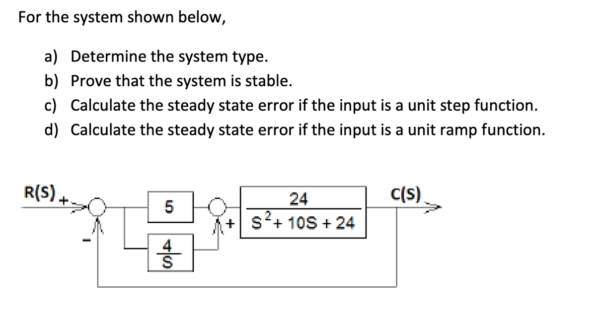

Transcribed Image Text:For the system shown below,
a) Determine the system type.
b) Prove that the system is stable.
c) Calculate the steady state error if the input is a unit step function.
d) Calculate the steady state error if the input is a unit ramp function.
C(S)
R(S) +
5
SA
24
+ S²+ 10S + 24
Expert Solution
This question has been solved!
Explore an expertly crafted, step-by-step solution for a thorough understanding of key concepts.

Step by stepSolved in 7 steps with 5 images

Knowledge Booster


Learn more about
Need a deep-dive on the concept behind this application? Look no further. Learn more about this topic, electrical-engineering and related others by exploring similar questions and additional content below.Similar questions
- In a short essay of fewer than 500 words, explain the oscillator design procedure. Please explain in terms of amplifier type selection, amplifier design, resonator design, linear oscillator analysis, and Nonlinear Oscillator Analysis. Thanks.arrow_forwardPlease answer in typing format solution please only typing format solution please only typing format Please answer in typing format solution please only typing formatarrow_forwardoccurs when the opamp output voltage is capped at a level just below the power supply voltage (does not increase beyond this value) even as input rises. O electrical isolation O opamp mismatch O slew rate distortion saturationarrow_forward
- Figures (a) and (b) below show two systems that might be used to control the temperature of a room. Explain how each operates. Reference voltage (a) Differential amplifier (b) Electrical power [4 Set point Electronic switch Relay Heater Heater Resistance to voltage converter Electrical power Microcontroller Thermistor Thermistor Analogue-to Resistance to digital converter voltage convertarrow_forwardLabel input and output of diagram?arrow_forward
arrow_back_ios
arrow_forward_ios
Recommended textbooks for you
- Introductory Circuit Analysis (13th Edition)Electrical EngineeringISBN:9780133923605Author:Robert L. BoylestadPublisher:PEARSON
 Delmar's Standard Textbook Of ElectricityElectrical EngineeringISBN:9781337900348Author:Stephen L. HermanPublisher:Cengage Learning
 Programmable Logic ControllersElectrical EngineeringISBN:9780073373843Author:Frank D. PetruzellaPublisher:McGraw-Hill Education
  Fundamentals of Electric CircuitsElectrical EngineeringISBN:9780078028229Author:Charles K Alexander, Matthew SadikuPublisher:McGraw-Hill Education
 Electric Circuits. (11th Edition)Electrical EngineeringISBN:9780134746968Author:James W. Nilsson, Susan RiedelPublisher:PEARSON
 Engineering ElectromagneticsElectrical EngineeringISBN:9780078028151Author:Hayt, William H. (william Hart), Jr, BUCK, John A.Publisher:Mcgraw-hill Education,
Introductory Circuit Analysis (13th Edition)
Electrical Engineering
ISBN:9780133923605
Author:Robert L. Boylestad
Publisher:PEARSON
Delmar's Standard Textbook Of Electricity
Electrical Engineering
ISBN:9781337900348
Author:Stephen L. Herman
Publisher:Cengage Learning
Programmable Logic Controllers
Electrical Engineering
ISBN:9780073373843
Author:Frank D. Petruzella
Publisher:McGraw-Hill Education
Fundamentals of Electric Circuits
Electrical Engineering
ISBN:9780078028229
Author:Charles K Alexander, Matthew Sadiku
Publisher:McGraw-Hill Education
Electric Circuits. (11th Edition)
Electrical Engineering
ISBN:9780134746968
Author:James W. Nilsson, Susan Riedel
Publisher:PEARSON
Engineering Electromagnetics
Electrical Engineering
ISBN:9780078028151
Author:Hayt, William H. (william Hart), Jr, BUCK, John A.
Publisher:Mcgraw-hill Education,