
Structural Analysis
6th Edition
ISBN: 9781337630931
Author: KASSIMALI, Aslam.
Publisher: Cengage,
expand_more
expand_more
format_list_bulleted
Related questions
Concept explainers
Question
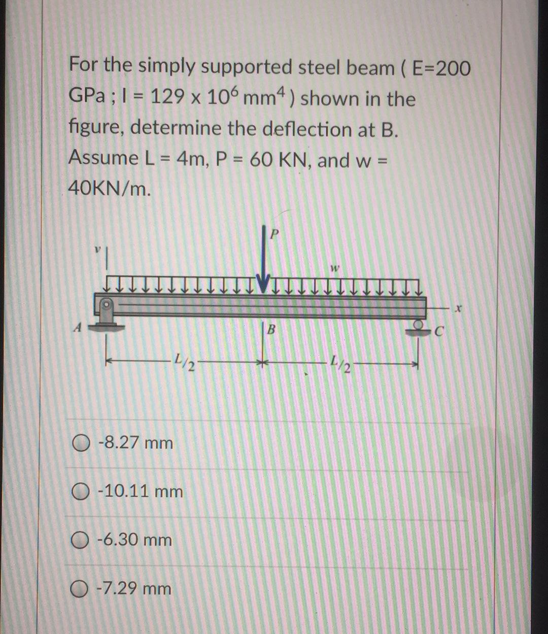

Transcribed Image Text:For the simply supported steel beam (E=200
GPa ; 1= 129 x 106 mm4) shown in the
figure, determine the deflection at B.
Assume L = 4m, P = 60 KN, and w =
40KN/m.
-8.27 mm
O-10.11 mm
O-6.30 mm
4/2
O -7.29 mm
B
W
L/27
C
Expert Solution
This question has been solved!
Explore an expertly crafted, step-by-step solution for a thorough understanding of key concepts.

Step by stepSolved in 2 steps with 1 images

Knowledge Booster


Learn more about
Need a deep-dive on the concept behind this application? Look no further. Learn more about this topic, civil-engineering and related others by exploring similar questions and additional content below.Similar questions
- For the beam shown: (a) determine the distance a for which the maximum positive and negative bending moments in the beam are equal; and (b) draw the corresponding shear and bending moment diagrams for the beam.arrow_forwardA beam is part of the framing system for the floor of an office building. The floor is subjected to both dead loads and live loads. The maximum moment caused by the service dead load is 45 ft-kips, and the maximum moment for the service live load is 63 ft-kips (these moments occur at the same location on the beam and can therefore be combined). a. If load and resistance factor design is used, determine the maximum factored bending moment (required moment strength). What is the controlling AISC load combination? b. What is the required nominal moment strength for a resistance factor of 0.90? c. If allowable strength design is used, determine the required moment strength. What is the controlling AISC lead combination? d. What is the required nominal moment strength for a safety factor of 1.67?arrow_forwardRefer to Figure P6.4. A strip load of q = 900 lb/ft2 is applied over a width B = 36 ft. Determine the increase in vertical stress at point A located z = 15 ft below the surface. Given: x = 27 ft. Figure P6.4arrow_forward
Recommended textbooks for you
 Steel Design (Activate Learning with these NEW ti...Civil EngineeringISBN:9781337094740Author:Segui, William T.Publisher:Cengage Learning
 Materials Science And Engineering PropertiesCivil EngineeringISBN:9781111988609Author:Charles GilmorePublisher:Cengage Learning
 Principles of Foundation Engineering (MindTap Cou...Civil EngineeringISBN:9781305081550Author:Braja M. DasPublisher:Cengage Learning
Steel Design (Activate Learning with these NEW ti...
Civil Engineering
ISBN:9781337094740
Author:Segui, William T.
Publisher:Cengage Learning
Materials Science And Engineering Properties
Civil Engineering
ISBN:9781111988609
Author:Charles Gilmore
Publisher:Cengage Learning
Principles of Foundation Engineering (MindTap Cou...
Civil Engineering
ISBN:9781305081550
Author:Braja M. Das
Publisher:Cengage Learning