
Structural Analysis
6th Edition
ISBN: 9781337630931
Author: KASSIMALI, Aslam.
Publisher: Cengage,
expand_more
expand_more
format_list_bulleted
Related questions
Concept explainers
Question
thumb_up100%
In solving the problem, use conjugate beam method.
Subject: Structural Theory
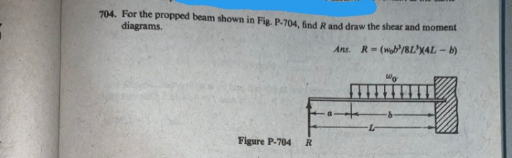

Transcribed Image Text:704. For the propped beam shown in Fig. P-704, find Rand draw the shear and moment
diagrams.
Ans.
R=(wob/8L*X4L - b)
Wo
Figure P-704
R
Expert Solution
This question has been solved!
Explore an expertly crafted, step-by-step solution for a thorough understanding of key concepts.
Step 1: Basics of conjugate beam
VIEW Step 2: Find the bending moment diagram of real beam
VIEW Step 3: real beam conversion into conjugate beam
VIEW Step 4: loading on conjugate beam and find the value of R
VIEW Step 5: Find the value of Reactions
VIEW Step 6: shear force and Bending moment diagram
VIEW 
Step by stepSolved in 6 steps with 6 images

Knowledge Booster


Learn more about
Need a deep-dive on the concept behind this application? Look no further. Learn more about this topic, civil-engineering and related others by exploring similar questions and additional content below.Similar questions
- please help, thanksarrow_forwardElementary beam theory predicts that the axial bending stress ox in a prismatic beam is given by: ox = (M.I,M,L)y+(M,I.-M.I.) (1,1₂-13/2) where My and M₂ are bending moments applied to a cross-section, and where ly, lz and lyz are second moments of area in the usual notation (Oxyz is a Cartesian coordinate system in which the x axis corresponds to the centroidal axis of the beam). (iii) A Z--section beam has the cross-section shown overleaf (see Figure QB2). The second moments of area of the section about the y and z axes are given as;; ly = 1.12x106mm² and I₂ = 2.87x106 mm4. Show that lyz = 1.35x106 mm² (use the parallel axis theorem). 100 60 10 y -10 10 60 Figure QB2 N (iv) Bending moments Mz = 2.0 kNm and My = 0 kNm act on a cross- -section of the beam of part (iii). Obtain an expression for the bending stress and sketch the orientation of the neutral axis with reference to the y and z axes. What is the maximum tensile value of the axial bending stress and where does it occur?arrow_forwardWrite the number of elements, nodes required and degree of freedom to solve following truss using FEM (Use the best node/element numbering; Do not need to solve it!) Would ANSYS be able to solve the structure with given Boundary Conditions (BC)? If not, what should be done and why?arrow_forward
arrow_back_ios
arrow_forward_ios
Recommended textbooks for you
 Structural Analysis (10th Edition)Civil EngineeringISBN:9780134610672Author:Russell C. HibbelerPublisher:PEARSON
 Principles of Foundation Engineering (MindTap Cou...Civil EngineeringISBN:9781337705028Author:Braja M. Das, Nagaratnam SivakuganPublisher:Cengage Learning
 Fundamentals of Structural AnalysisCivil EngineeringISBN:9780073398006Author:Kenneth M. Leet Emeritus, Chia-Ming Uang, Joel LanningPublisher:McGraw-Hill Education
 Traffic and Highway EngineeringCivil EngineeringISBN:9781305156241Author:Garber, Nicholas J.Publisher:Cengage Learning
Structural Analysis (10th Edition)
Civil Engineering
ISBN:9780134610672
Author:Russell C. Hibbeler
Publisher:PEARSON
Principles of Foundation Engineering (MindTap Cou...
Civil Engineering
ISBN:9781337705028
Author:Braja M. Das, Nagaratnam Sivakugan
Publisher:Cengage Learning
Fundamentals of Structural Analysis
Civil Engineering
ISBN:9780073398006
Author:Kenneth M. Leet Emeritus, Chia-Ming Uang, Joel Lanning
Publisher:McGraw-Hill Education
Traffic and Highway Engineering
Civil Engineering
ISBN:9781305156241
Author:Garber, Nicholas J.
Publisher:Cengage Learning