
Introductory Circuit Analysis (13th Edition)
13th Edition
ISBN: 9780133923605
Author: Robert L. Boylestad
Publisher: PEARSON
expand_more
expand_more
format_list_bulleted
Related questions
Concept explainers
Question
For the power system in the fig. below the magnitudes of the sending and
receiving end voltages are 1pu. The related loads are:
S1 = 6 + j10 and S2 = 14 + j8
The generation to the busbars are rated:
10 + j15 at bus 1 and 10 + j3 at bus 2. The impedance of the line is j0.05pu. The
active power at each end of the busbar is 10 pu. Calculate the following:
Load angle, Sending end voltage ,Reactive power at the sending end ,
Reactive power at the receiving end ,Total reactive power in the transmission line , Load at bus 1 , Power factor at bus 1 ,Load at bus 2 ,
and Power factor at bus 2.
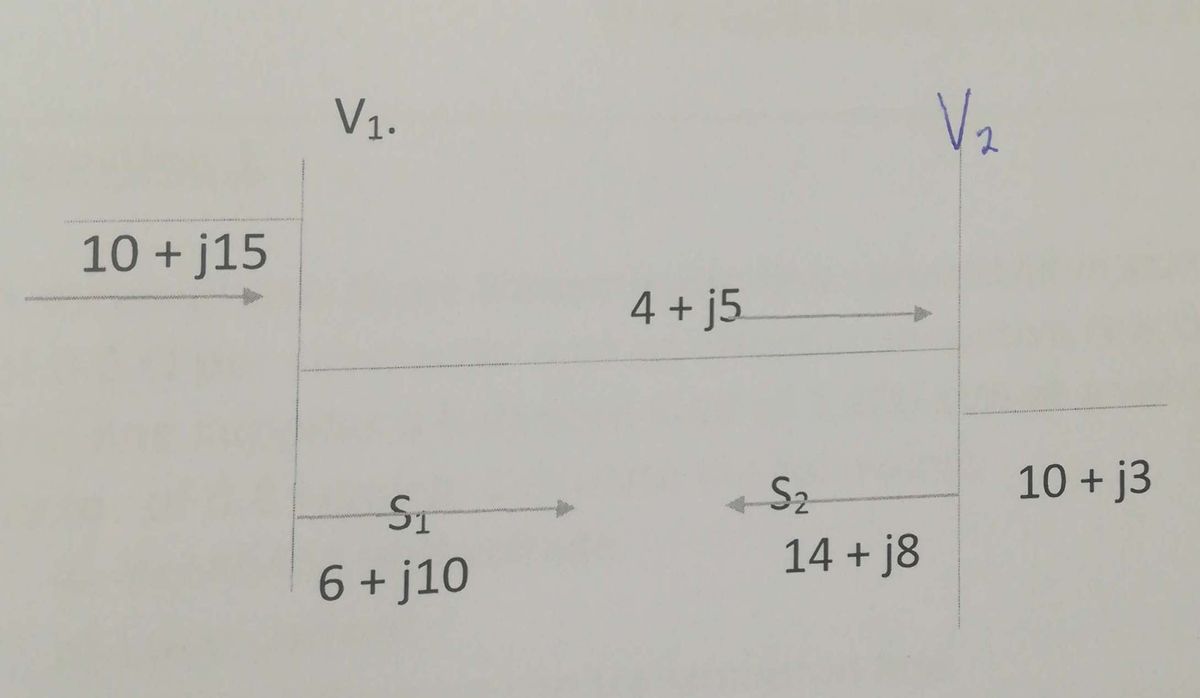

Transcribed Image Text:V1.
Vz
10 + j15
4 + j5.
S2
10 + j3
ST
14 + j8
6 + j10
Expert Solution
This question has been solved!
Explore an expertly crafted, step-by-step solution for a thorough understanding of key concepts.

Step by stepSolved in 3 steps with 3 images

Knowledge Booster


Learn more about
Need a deep-dive on the concept behind this application? Look no further. Learn more about this topic, electrical-engineering and related others by exploring similar questions and additional content below.Similar questions
- 1 PROBLEM 20020° V rms, Vbn 1. A balanced three-phase Y-Y system has the phase voltages of Van 200/120° V rms, and Ven = 2002(-120°) Vrms. The load impedance per phase is Z₁ = 50 - j100 n. a Van Vcn n Vbn Ia Ib Ic B Zu (b) Determine the line currents Īa, Ip and Īc. (c) Determine the total average power delivered to the three loads. N C = ZL (a) The balanced three-phase circuit has a negative phase sequence. Circle your choice. (1) True (ii) Falsearrow_forwardA short link has a thermal rating of 1.0 MVA, and a phase impedance of 140 /50.7°. The receiving end voltage needs to be kept at 11 kV, and the sending end voltage must not be more than 10% above this when the link is fully loaded. Sketch a phasor diagram for the loaded link, and hence determine the active and reactive powers that could be delivered in this condition. 947 kW; 321kVAr laggingarrow_forwardWrite the power flow equations A) Power system 1: j0.5 Bus 1: V1=1.0,81=0 Bus 2: V2=1.04, P G2=1.0 P12=0.3, Q12=0.1 Bus 3: P13=0.5,Q=0.3 j0.2 j0.3= j0.1 j0.4 j0.3 j0.1 3 j0.3arrow_forward
Recommended textbooks for you
- Introductory Circuit Analysis (13th Edition)Electrical EngineeringISBN:9780133923605Author:Robert L. BoylestadPublisher:PEARSON
 Delmar's Standard Textbook Of ElectricityElectrical EngineeringISBN:9781337900348Author:Stephen L. HermanPublisher:Cengage Learning
 Programmable Logic ControllersElectrical EngineeringISBN:9780073373843Author:Frank D. PetruzellaPublisher:McGraw-Hill Education
  Fundamentals of Electric CircuitsElectrical EngineeringISBN:9780078028229Author:Charles K Alexander, Matthew SadikuPublisher:McGraw-Hill Education
 Electric Circuits. (11th Edition)Electrical EngineeringISBN:9780134746968Author:James W. Nilsson, Susan RiedelPublisher:PEARSON
 Engineering ElectromagneticsElectrical EngineeringISBN:9780078028151Author:Hayt, William H. (william Hart), Jr, BUCK, John A.Publisher:Mcgraw-hill Education,
Introductory Circuit Analysis (13th Edition)
Electrical Engineering
ISBN:9780133923605
Author:Robert L. Boylestad
Publisher:PEARSON
Delmar's Standard Textbook Of Electricity
Electrical Engineering
ISBN:9781337900348
Author:Stephen L. Herman
Publisher:Cengage Learning
Programmable Logic Controllers
Electrical Engineering
ISBN:9780073373843
Author:Frank D. Petruzella
Publisher:McGraw-Hill Education
Fundamentals of Electric Circuits
Electrical Engineering
ISBN:9780078028229
Author:Charles K Alexander, Matthew Sadiku
Publisher:McGraw-Hill Education
Electric Circuits. (11th Edition)
Electrical Engineering
ISBN:9780134746968
Author:James W. Nilsson, Susan Riedel
Publisher:PEARSON
Engineering Electromagnetics
Electrical Engineering
ISBN:9780078028151
Author:Hayt, William H. (william Hart), Jr, BUCK, John A.
Publisher:Mcgraw-hill Education,