Structural Analysis
6th Edition
ISBN: 9781337630931
Author: KASSIMALI, Aslam.
Publisher: Cengage,
expand_more
expand_more
format_list_bulleted
Question

Transcribed Image Text:For the loading shown below, w = 0.37, P = 4.2, a = 6.2 and L = 24 (the figure has a lower-case L). Determine the maximum moment from the tables using superposition. Give your
answer to one decimal place.
a
/2
/2
Type your answer..

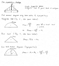
Transcribed Image Text:Two symmetric loadings
Simply suppor ted beam
triangu lar load & point loq d at midspan
Find moment. diagram us ing baam tables & Super posi tion
Triang Io
lar lood. (fig. 6, NDS
beam. dables)
We
Mmat
Note W is to tal
%3D
we/2
in
Mmax =
= M,
12
Poiat. load
I fig. 7
beam tabler)
NDS
Mmax
Mz
Sum both moment diograms (supre pasition)
M MUA
M,
we? Pl
12
My t Mz.
%3D
%3D
M2
Expert Solution
arrow_forward
Step 1
Given:
The value of w is 0.37.
The value of P is 4.2.
The value of L is 24.
The value of a is 6.2.
Step by stepSolved in 5 steps with 1 images

Knowledge Booster
Learn more about
Need a deep-dive on the concept behind this application? Look no further. Learn more about this topic, civil-engineering and related others by exploring similar questions and additional content below.Similar questions
- A cantilever beam is supported by a column at its end as shown in Figure (a) below. Figure (b) below shows the cross sectional view of the beam and the column. Per the applied moment at its end, 3 No. 10 bars are required at the top of the beam with an effective depth = 21 in. Given: for the beam, fe' = 3000 psi (light weight), and fy = 60,000 psi; for the column, fe=5000 psi (normal weight). All the bars are not epoxy-coated. (a) Per ACI 318-19's simplified equation, calculate the required development length in the beam for straight bars. Is the space in the beam adequate to develop straight bars? (b) Knowing that the No. 3 U-stirrups with a constant spacing of 10.5 inches are used as the shear reinforcement in the beam and the concrete clear cover thickness is 1.5 inches, use Sec 25.4.2.3 to recalculate the required development length of straight No. 11 bars. Is the space adequate to develop straight bars in the beam? If not, provide your recommendation on how to develop the bars in…arrow_forwardQ2 In the figure below, R is the resultant of the two forces F1 and F2. Determine the magnitude and direction of the force F2 F1 = 150 N Clox R = 280N 32arrow_forwardSolve the problem by the moment-area method. The beam has constant flexural rigidity EI. A simple beam AB supports two concentrated loads P at the positions shown in the figure. B C 4. 4 A support C at the midpoint of the beam is positioned at distance d below the beam before the loads are applied. Assuming that d = 12 mm, L = 5.4 m, E = 200 GPa, and I = 193 x 10° mm, calculate the magnitude of the loads P (in kN) so that the beam just touches the support at C. 163.87 x kNarrow_forward
- Draw the moment diagram for the beam AB and AC. Then, determine the slope to the left and right of B and the displacement at B using the conjugate-beam method. Take E=200GPa, IAB=60(106)mm4 and IBC=30(106)mm4.arrow_forwardConsider the beam shown in (Figure 1). EIEI is a constant. Suppose that www = 19 kN/mkN/m.arrow_forward
arrow_back_ios
arrow_forward_ios
Recommended textbooks for you

 Structural Analysis (10th Edition)Civil EngineeringISBN:9780134610672Author:Russell C. HibbelerPublisher:PEARSON
 Principles of Foundation Engineering (MindTap Cou...Civil EngineeringISBN:9781337705028Author:Braja M. Das, Nagaratnam SivakuganPublisher:Cengage Learning
 Fundamentals of Structural AnalysisCivil EngineeringISBN:9780073398006Author:Kenneth M. Leet Emeritus, Chia-Ming Uang, Joel LanningPublisher:McGraw-Hill Education
 Traffic and Highway EngineeringCivil EngineeringISBN:9781305156241Author:Garber, Nicholas J.Publisher:Cengage Learning


Structural Analysis (10th Edition)
Civil Engineering
ISBN:9780134610672
Author:Russell C. Hibbeler
Publisher:PEARSON

Principles of Foundation Engineering (MindTap Cou...
Civil Engineering
ISBN:9781337705028
Author:Braja M. Das, Nagaratnam Sivakugan
Publisher:Cengage Learning

Fundamentals of Structural Analysis
Civil Engineering
ISBN:9780073398006
Author:Kenneth M. Leet Emeritus, Chia-Ming Uang, Joel Lanning
Publisher:McGraw-Hill Education


Traffic and Highway Engineering
Civil Engineering
ISBN:9781305156241
Author:Garber, Nicholas J.
Publisher:Cengage Learning