Elements Of Electromagnetics
7th Edition
ISBN: 9780190698614
Author: Sadiku, Matthew N. O.
Publisher: Oxford University Press
expand_more
expand_more
format_list_bulleted
Concept explainers
Question
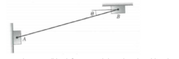
For the kinematic diagram shown in figure P7.22, the length of link AB is 100 mm and θ =
35°. Box A moves upward at a velocity of 10 mm/s and accelerates at 5 mm/s2. At the same
time, the velocity of box B is 7 mm/s and accelerates at a rate of 25 mm/s2. Draw the
acceleration
to B and the linear acceleration of A with respect to B

Transcribed Image Text:The image depicts a simple mechanical diagram involving two points, A and B. Point A is located on a vertical plane, while point B is positioned on a horizontal plane. A line connects the two points, forming an angle θ with the horizontal plane.
**Diagram Details:**
- **Point A:** Situated on the left side of the diagram, attached to what seems to be a vertical structure.
- **Point B:** Located on the upper right side of the diagram, connected to a horizontal plane.
- **Connecting Line:** A straight line drawn from point A to point B.
- **Angle θ (Theta):** The angle formed between the connecting line and the horizontal plane where point B is located.
This setup is often used in physics and engineering to analyze forces, tensions, or angles in structures or systems.
Expert Solution
This question has been solved!
Explore an expertly crafted, step-by-step solution for a thorough understanding of key concepts.
This is a popular solution
Trending nowThis is a popular solution!
Step by stepSolved in 4 steps with 5 images

Knowledge Booster
Learn more about
Need a deep-dive on the concept behind this application? Look no further. Learn more about this topic, mechanical-engineering and related others by exploring similar questions and additional content below.Similar questions
- PE P4 P3 P2 P1 7.5 35 Using the turning method, write down the positions of the five points shown in the figure above and the corresponding coordinates Points Position specification in absolute dimension P1 P2 P3 P4 P5arrow_forwardIn the mechanism shown below, link AB rotates at a constant angular velocity of 1.5 rad per sec counterclockwise. What is the acceleration of C along the channel? Assume the positive direction to be upwards and to the right. use relative motionarrow_forwardNeeds Complete typed solution with 100 % accuracy.arrow_forward
arrow_back_ios
arrow_forward_ios
Recommended textbooks for you
 Elements Of ElectromagneticsMechanical EngineeringISBN:9780190698614Author:Sadiku, Matthew N. O.Publisher:Oxford University Press
 Mechanics of Materials (10th Edition)Mechanical EngineeringISBN:9780134319650Author:Russell C. HibbelerPublisher:PEARSON
 Thermodynamics: An Engineering ApproachMechanical EngineeringISBN:9781259822674Author:Yunus A. Cengel Dr., Michael A. BolesPublisher:McGraw-Hill Education
 Control Systems EngineeringMechanical EngineeringISBN:9781118170519Author:Norman S. NisePublisher:WILEY
 Mechanics of Materials (MindTap Course List)Mechanical EngineeringISBN:9781337093347Author:Barry J. Goodno, James M. GerePublisher:Cengage Learning
 Engineering Mechanics: StaticsMechanical EngineeringISBN:9781118807330Author:James L. Meriam, L. G. Kraige, J. N. BoltonPublisher:WILEY

Elements Of Electromagnetics
Mechanical Engineering
ISBN:9780190698614
Author:Sadiku, Matthew N. O.
Publisher:Oxford University Press

Mechanics of Materials (10th Edition)
Mechanical Engineering
ISBN:9780134319650
Author:Russell C. Hibbeler
Publisher:PEARSON

Thermodynamics: An Engineering Approach
Mechanical Engineering
ISBN:9781259822674
Author:Yunus A. Cengel Dr., Michael A. Boles
Publisher:McGraw-Hill Education

Control Systems Engineering
Mechanical Engineering
ISBN:9781118170519
Author:Norman S. Nise
Publisher:WILEY

Mechanics of Materials (MindTap Course List)
Mechanical Engineering
ISBN:9781337093347
Author:Barry J. Goodno, James M. Gere
Publisher:Cengage Learning

Engineering Mechanics: Statics
Mechanical Engineering
ISBN:9781118807330
Author:James L. Meriam, L. G. Kraige, J. N. Bolton
Publisher:WILEY