Introductory Circuit Analysis (13th Edition)
13th Edition
ISBN: 9780133923605
Author: Robert L. Boylestad
Publisher: PEARSON
expand_more
expand_more
format_list_bulleted
Concept explainers
Question
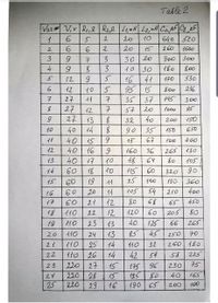
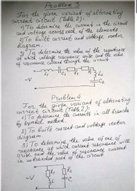
How to solve problems 3 and 4 (the second option in the table)?

Transcribed Image Text:Table 2
Var# V,v R,e R2,24,MHL2, nH Ci, juF|C2 ,AF|
640 520
5
2.
20
10
2.
2.
20
15
260
1600
3
7.
3
30 20
Joo
300
4
3.
イo|30
180
800
12
16
41
170
530
12
10
5
95 15
800
236
7
27
イイ
子
35
37
145
300
27
27
イ2
7
57
20
1o00
95
13
32
40
イ50
200
10
40
14
35
150
650
イイ
40
15
6.
15
67
イOo
400
イ2
40
16
160
36
265
イ30
13
40
イ7
10
48
64
80
105
14
60
18
イO
115
60
320
go
15
60
19
イイ
25
100
130
360
16
60
20
1イ
イ05
54
210
400
イ7
60
21
12
80
68
65
450
イ20
|イイO
23
イイの
イ10
18
22
12
60
205
80
19
10
13
40
125
66
265
20
24
13
85
45
250
70
14
25
14
イ0
32
260|イ80
イイ0| 26
220 27
22
42
54
38
225
23
15
175 96
230
75
24
220
28
15
12580
40
165
25
220
29
16
190 65
100
200
|の

Transcribed Image Text:Problem 3
For the given variant of alterna ting
Cuzrent circuit (Table 2):
1) To deter mine the current in the citcuit
and voltage across each of the elements.
2) To built current and vobtage voetor
diagram.
3)Ta determine the ralue of the regctance
at which voltage resonance, arise and the value
of resonance currens through the circuit.
C2
Problem 4
For, the given variaut of altezna ting
current cirEuit (Table 2):
1) To determine the currents in all brenches
by gymbol method.
2) To built cur rent and voltage veetor
diágram.
3) To determine the value of ore of
reactance at which current resonancewill
arise anod the 'value of resohance current
in un branched part of the circuit
34
Expert Solution
arrow_forward
Step 1
We are authorized to answer one question at a time, since you have not mentioned which question you are looking for, so we are answering the first one(problem no.3). Please repost your question separately for the remaining question.
Here supply voltage frequency is not given so we will assume supply frequency as 'f' and obtain the answers in terms of s
' f '
arrow_forward
Step 2
Problem 3:
From the second option of the table
R1=6
V=6 V
arrow_forward
Step 3
1) Given circuit is RLC series circuit and hence current will be remain same in all the elements.
arrow_forward
Step 4
1)Current in the circuit
voltage across each element
Step by stepSolved in 7 steps with 1 images

Knowledge Booster
Learn more about
Need a deep-dive on the concept behind this application? Look no further. Learn more about this topic, electrical-engineering and related others by exploring similar questions and additional content below.Similar questions
- Hi, I was given this circuit and I have been asked to find the maximum current i that would flow in the circuit if the value Rt and Rd had very low (negligible) values. Can you help me with it?arrow_forwardSolve step by step. Please solve fast.arrow_forward5. Determine the expression of the total resistance of the following circuit for each case 1. S1 open S2 open 2. S1 close S2 open 3. Sl open S2 close 4. S1 close S2 close $1 R1 ㅔ R3 ww S2 R2 www R4arrow_forward
Recommended textbooks for you
 Introductory Circuit Analysis (13th Edition)Electrical EngineeringISBN:9780133923605Author:Robert L. BoylestadPublisher:PEARSON
 Delmar's Standard Textbook Of ElectricityElectrical EngineeringISBN:9781337900348Author:Stephen L. HermanPublisher:Cengage Learning
 Programmable Logic ControllersElectrical EngineeringISBN:9780073373843Author:Frank D. PetruzellaPublisher:McGraw-Hill Education
 Fundamentals of Electric CircuitsElectrical EngineeringISBN:9780078028229Author:Charles K Alexander, Matthew SadikuPublisher:McGraw-Hill Education
 Electric Circuits. (11th Edition)Electrical EngineeringISBN:9780134746968Author:James W. Nilsson, Susan RiedelPublisher:PEARSON
 Engineering ElectromagneticsElectrical EngineeringISBN:9780078028151Author:Hayt, William H. (william Hart), Jr, BUCK, John A.Publisher:Mcgraw-hill Education,

Introductory Circuit Analysis (13th Edition)
Electrical Engineering
ISBN:9780133923605
Author:Robert L. Boylestad
Publisher:PEARSON

Delmar's Standard Textbook Of Electricity
Electrical Engineering
ISBN:9781337900348
Author:Stephen L. Herman
Publisher:Cengage Learning

Programmable Logic Controllers
Electrical Engineering
ISBN:9780073373843
Author:Frank D. Petruzella
Publisher:McGraw-Hill Education

Fundamentals of Electric Circuits
Electrical Engineering
ISBN:9780078028229
Author:Charles K Alexander, Matthew Sadiku
Publisher:McGraw-Hill Education

Electric Circuits. (11th Edition)
Electrical Engineering
ISBN:9780134746968
Author:James W. Nilsson, Susan Riedel
Publisher:PEARSON

Engineering Electromagnetics
Electrical Engineering
ISBN:9780078028151
Author:Hayt, William H. (william Hart), Jr, BUCK, John A.
Publisher:Mcgraw-hill Education,