Structural Analysis
6th Edition
ISBN: 9781337630931
Author: KASSIMALI, Aslam.
Publisher: Cengage,
expand_more
expand_more
format_list_bulleted
Concept explainers
Question

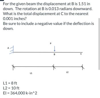
Transcribed Image Text:For the given beam the displacement at B is 1.51 in
down. The rotation at B is 0.013 radians downward.
What is the total displacement at C to the nearest
0.001 inches?
Be sure to include a negative value if the deflection is
down.
엊
A
X
L1
L1 = 8 ft
L2 = 10 ft
El = 364,000 k-in^2
D
↓
B
L2
Expert Solution
This question has been solved!
Explore an expertly crafted, step-by-step solution for a thorough understanding of key concepts.
This is a popular solution
Trending nowThis is a popular solution!
Step by stepSolved in 2 steps with 1 images

Knowledge Booster
Learn more about
Need a deep-dive on the concept behind this application? Look no further. Learn more about this topic, civil-engineering and related others by exploring similar questions and additional content below.Similar questions
- A 10 m long beam has a 3 kN point load applied to the cantilever steel beam. The load is applied 4 m from the support as shown below. Assuming that E-2×10°N/mm² and I =20×10°mm" a Figure 3 a) Calculate deflection at B in mm. Please insert - sign if the deflection is downward. Deflection at B = mm b) Calculate deflection at C in mm. Please insert – sign if the deflection is downward. Deflection at C= mmarrow_forwardUse integration methodarrow_forwardAssume a constant value of EI = 560×10° N-mm² for the beam. A 210 N-m 200 mm Determine the deflection of the beam at C. Answer in mm rounded-off to 2 decimal places. B 150 mm C 100 1,400 N D 250 mm E Xarrow_forward
- Problem 4 The cantilever beam shown below is loaded with a concentrated moment at free end B. Determine: a) the vertical deflection at B, b) the rotation at B nim A L = 10 ft I= 4900 in E = 29000 ksi B M₁ = 80 k-/arrow_forwardI need another solution please.arrow_forwardassume that a max deflection is equal to(length/1000)mm is to be the limiting factor in selecting a W-beam having a span length of 1.47meters. Supports are at both ends and the load at the center is 24.70kN. I=71,276,243mm^4. Determine the minimum material stiffness(Young's Modulus) inGPa.arrow_forward
- For the beam and loading shown, determine the deflection at point C in inches. Indicate the negative sign if it's downward. Use E=29x10° psi. y P = 35 kips C a = 5 ft L = 15 ft B I W 10 x 19arrow_forwardFor the beam and loading shown, use discontinuity functions to compute (a) the slope of the beam at B and (b) the deflection of the beam at C. Assume a constant value of El = 27 x 106 lb-ft² for the beam; w₁ = 6200 lb/ft, LAB = 7.0 ft, Lgc = 15 ft. Lcd = 8 ft. Wo X LBC LCD LAB Answer: (a) 0g = (b) vc= B rad in. Darrow_forwardHorizontal Deflection at joint D using Virtual Work Methodarrow_forward
arrow_back_ios
arrow_forward_ios
Recommended textbooks for you

 Structural Analysis (10th Edition)Civil EngineeringISBN:9780134610672Author:Russell C. HibbelerPublisher:PEARSON
 Principles of Foundation Engineering (MindTap Cou...Civil EngineeringISBN:9781337705028Author:Braja M. Das, Nagaratnam SivakuganPublisher:Cengage Learning
 Fundamentals of Structural AnalysisCivil EngineeringISBN:9780073398006Author:Kenneth M. Leet Emeritus, Chia-Ming Uang, Joel LanningPublisher:McGraw-Hill Education
 Traffic and Highway EngineeringCivil EngineeringISBN:9781305156241Author:Garber, Nicholas J.Publisher:Cengage Learning


Structural Analysis (10th Edition)
Civil Engineering
ISBN:9780134610672
Author:Russell C. Hibbeler
Publisher:PEARSON

Principles of Foundation Engineering (MindTap Cou...
Civil Engineering
ISBN:9781337705028
Author:Braja M. Das, Nagaratnam Sivakugan
Publisher:Cengage Learning

Fundamentals of Structural Analysis
Civil Engineering
ISBN:9780073398006
Author:Kenneth M. Leet Emeritus, Chia-Ming Uang, Joel Lanning
Publisher:McGraw-Hill Education


Traffic and Highway Engineering
Civil Engineering
ISBN:9781305156241
Author:Garber, Nicholas J.
Publisher:Cengage Learning