Structural Analysis
6th Edition
ISBN: 9781337630931
Author: KASSIMALI, Aslam.
Publisher: Cengage,
expand_more
expand_more
format_list_bulleted
Concept explainers
Question

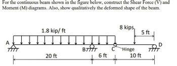
Transcribed Image Text:For the continuous beam shown in the figure below, construct the Shear Force (V) and
Moment (M) diagrams. Also, show qualitatively the deformed shape of the beam.
A
TTTT
1.8 kip/ ft
20 ft
BIT
*
6 ft
C
8 kips,
Hinge
5 ft
10 ft
त
D
Expert Solution
This question has been solved!
Explore an expertly crafted, step-by-step solution for a thorough understanding of key concepts.
Step by stepSolved in 4 steps with 4 images

Knowledge Booster
Learn more about
Need a deep-dive on the concept behind this application? Look no further. Learn more about this topic, civil-engineering and related others by exploring similar questions and additional content below.Similar questions
- PROBLEM 3. (30 PTS.) Use either the Portal Method or the Cantilever Method to approximate all the members' shear, moment and axial forces. Present your answer in the format presented by the SMA (for shear, moment and axial) in the figure below. 0.6P 8 M A P 3 M G D A 5 M 8m A H E B 5 M 8m A 1 F с 4m 4m P= 135kNarrow_forwarda b c d e 14.4 in 6.5 in 6.8 in 6.5 in 5.1 in A force of P = 110 lbf is applied at point D on the frame pictured above with the dimensions given in the table above. Determine the internal forces indicated in the table below. Forces: (Denote rightward or upward forces with positive values; leftward or downward forces with negative values.) FAX = ? FAY = ? FBX = ?arrow_forward
Recommended textbooks for you

 Structural Analysis (10th Edition)Civil EngineeringISBN:9780134610672Author:Russell C. HibbelerPublisher:PEARSON
 Principles of Foundation Engineering (MindTap Cou...Civil EngineeringISBN:9781337705028Author:Braja M. Das, Nagaratnam SivakuganPublisher:Cengage Learning
 Fundamentals of Structural AnalysisCivil EngineeringISBN:9780073398006Author:Kenneth M. Leet Emeritus, Chia-Ming Uang, Joel LanningPublisher:McGraw-Hill Education
 Traffic and Highway EngineeringCivil EngineeringISBN:9781305156241Author:Garber, Nicholas J.Publisher:Cengage Learning


Structural Analysis (10th Edition)
Civil Engineering
ISBN:9780134610672
Author:Russell C. Hibbeler
Publisher:PEARSON

Principles of Foundation Engineering (MindTap Cou...
Civil Engineering
ISBN:9781337705028
Author:Braja M. Das, Nagaratnam Sivakugan
Publisher:Cengage Learning

Fundamentals of Structural Analysis
Civil Engineering
ISBN:9780073398006
Author:Kenneth M. Leet Emeritus, Chia-Ming Uang, Joel Lanning
Publisher:McGraw-Hill Education


Traffic and Highway Engineering
Civil Engineering
ISBN:9781305156241
Author:Garber, Nicholas J.
Publisher:Cengage Learning