Introductory Circuit Analysis (13th Edition)
13th Edition
ISBN: 9780133923605
Author: Robert L. Boylestad
Publisher: PEARSON
expand_more
expand_more
format_list_bulleted
Question

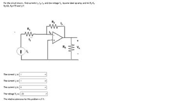
Transcribed Image Text:For the circuit shown, find currents 1, 2, 3, and the voltage V, Assume ideal op-amp, and tex R₁ =2,
Ry=20, Ro=170 and 1,-1
1
R₁
ww
R₂
The current l is: 1
The currently is: f
The current lg is:
The voltage V, 15: -20
The relative tolerance for this problem is 3%.
Ro
Vo
Expert Solution
This question has been solved!
Explore an expertly crafted, step-by-step solution for a thorough understanding of key concepts.
Step by stepSolved in 2 steps with 2 images

Knowledge Booster
Similar questions
- 3) Consider the Zener-diode voltage regulator shown below. Suppose you design this circuit to drive (supply) a load resistance RL. The supply voltages to the op-amp are +15 V and -15 V (not shown). a) What is Vout? b) If R = 1 k 2, what is the smallest R, that the circuit can handle without "sagging" the output voltage? c) What should be the power rating of the resistor R? Be explicit about your assumptions. +15 V R Vout IN4738 CS Scanned with CaScannerarrow_forwardPlease show the workarrow_forwardConsider the op-amp circuit to the right. Write a general formula for Vout as a function of Vin and the parameters of the resistor and MOSFET. Make sure to pay attention to the orientation of the MOSFET, you may assume an ideal op-amp. Vin R1 om + Q1 Voutarrow_forward
- I need help with Op-amp. tnxarrow_forwardQ4: Design a buck converter to produce an output voltage of 18 V across a 10-_ load resistor. The output voltage ripple must not exceed 0.5 percent. The dc supply is 48 V. Design for continuous inductor current. Specify the duty ratio, the switching frequency, the values of the inductor and capacitor, the peak voltage rating of each device, and the rms current in the inductor and capacitor. Assume ideal components. DEarrow_forwardConsider the following circuit using diode and Op-Amp. Assume ideal Op-Amp with output saturation at +-13V. Assume diode forward drop is 0.7V. a. Find Vo and VA when Vin = 1V and 3V. b. Find V, and VA when Vin = -1V and -3V. R Vin R VA ovo ER₂arrow_forward
- For this op-amp, there is an open-loop unity gain fT = 1.2 MHz and an open-loop gain Ao = 200,0000. a. What is the 3dB frequency for the open-loop op-amp, fb, and for the closed-loop circuit, f3dB? b. At f = 240 kHz, what is the value of the open-loop gain and the the closed-loop gain?arrow_forward(c) (d) Figure Figure Q1b shows an Op-amp with a bias current compensating resistor (Rp). R₁ V₂. Vp IB. R₂ W A • V₂ Figure Olb (i) Derive an expression for V. to quantify the effect of bias currents IB+ and IB-. [3] (ii) Explain how you would choose a value for Rp to reduce the output error due to the bias currents, IB+ and IB.. [3] Referring to an op-amp define what is meant by common-mode rejection ratio (CMRR) and explain the effect a finite CMRR would have on high-precision applications. [4] Page 2 of 7 Continued overleafarrow_forwardDiscuss what a difference amp is, give equations and details, what is a single-ended and differential signal, what is a 4-20 mA signal, what is common-mode noise and why is a difference amp used?arrow_forward
- 9. Suppose we design an inverting amplifier using 5% tolerance resistors and an ideal op-amp. The nominal amplifier gain is -20. Answer the following two questions: a. What are the minimum and maximum possible gains? b. What is the percent tolerance of the gain?arrow_forwardThe dc converter in the next figure has a resistive load, R = 15 and input voltage, Vs = 240 V. When the converter remains on, its voltage drop is Vch = 1.75 V and chopping) frequency is f = 15 kHz. If the duty cycle is 90%, determine (a) the average output voltage Va, (b) the rms output voltage Vo, € the converter efficiency, (d) the effective input resistance Ri, and € the rms value of the fundamental component of harmonics on the output voltage. + VH Converter Vs t=0 + SW ίο 01 Rarrow_forwardEx) A standard two-junction thermocouple configuration is being used to measure the temperature in a wind tunnel. The reference junction is held at a constant temperature of 10 °C. We have only a thermocouple table referenced to 0 °C. Determine the output voltage when the measuring junction is exposed to an air temperature of 100 °C.arrow_forward
arrow_back_ios
SEE MORE QUESTIONS
arrow_forward_ios
Recommended textbooks for you
 Introductory Circuit Analysis (13th Edition)Electrical EngineeringISBN:9780133923605Author:Robert L. BoylestadPublisher:PEARSON
 Delmar's Standard Textbook Of ElectricityElectrical EngineeringISBN:9781337900348Author:Stephen L. HermanPublisher:Cengage Learning
 Programmable Logic ControllersElectrical EngineeringISBN:9780073373843Author:Frank D. PetruzellaPublisher:McGraw-Hill Education
 Fundamentals of Electric CircuitsElectrical EngineeringISBN:9780078028229Author:Charles K Alexander, Matthew SadikuPublisher:McGraw-Hill Education
 Electric Circuits. (11th Edition)Electrical EngineeringISBN:9780134746968Author:James W. Nilsson, Susan RiedelPublisher:PEARSON
 Engineering ElectromagneticsElectrical EngineeringISBN:9780078028151Author:Hayt, William H. (william Hart), Jr, BUCK, John A.Publisher:Mcgraw-hill Education,

Introductory Circuit Analysis (13th Edition)
Electrical Engineering
ISBN:9780133923605
Author:Robert L. Boylestad
Publisher:PEARSON

Delmar's Standard Textbook Of Electricity
Electrical Engineering
ISBN:9781337900348
Author:Stephen L. Herman
Publisher:Cengage Learning

Programmable Logic Controllers
Electrical Engineering
ISBN:9780073373843
Author:Frank D. Petruzella
Publisher:McGraw-Hill Education

Fundamentals of Electric Circuits
Electrical Engineering
ISBN:9780078028229
Author:Charles K Alexander, Matthew Sadiku
Publisher:McGraw-Hill Education

Electric Circuits. (11th Edition)
Electrical Engineering
ISBN:9780134746968
Author:James W. Nilsson, Susan Riedel
Publisher:PEARSON

Engineering Electromagnetics
Electrical Engineering
ISBN:9780078028151
Author:Hayt, William H. (william Hart), Jr, BUCK, John A.
Publisher:Mcgraw-hill Education,