
Introductory Circuit Analysis (13th Edition)
13th Edition
ISBN: 9780133923605
Author: Robert L. Boylestad
Publisher: PEARSON
expand_more
expand_more
format_list_bulleted
Related questions
Concept explainers
Question
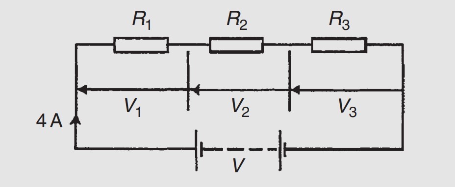
For the circuit shown below determine (a) the battery voltage V, (b) the total resistance of the circuit, and (c) the values of resistors R1, R2, and R3, given that the p.d.s across R1, R2 and R3 are 5 V, 2 V, and 6 V, respectively.

Transcribed Image Text:R1
R2
R3
V1
V2
V3
4 A
V
Expert Solution
This question has been solved!
Explore an expertly crafted, step-by-step solution for a thorough understanding of key concepts.

This is a popular solution

Trending nowThis is a popular solution!

Step by stepSolved in 2 steps with 2 images

Knowledge Booster


Learn more about
Need a deep-dive on the concept behind this application? Look no further. Learn more about this topic, electrical-engineering and related others by exploring similar questions and additional content below.Similar questions
- Can you please help me with this problem?arrow_forwardB 12 V (+ 32 kn I, A 1 kM 2 kN 1 kN 2 mA Darrow_forward5. The resistors, labeled A through F, in the following circuit represent incandescent lightbulbs which are dimmable. By "dimmable," we mean the amount of light a bulb produces is proportional to the voltage across the bulb (or, correspondingly, the current through the bulb). The resistances of all these bulbs is constant and they all have the same resistance. Assuming the voltage source is sufficient to cause all these bulbs to produce at least some illumination, rank the bulbs from brightest to dimmest (if two bulbs are equally bright, note this fact). Justify your answer. You should be able to do this without using equations. (However, if you want to resort to an equation or two to help you sort this out or discuss your solution, that's okay.) V₂ + B E www www F Marrow_forward
- A circuit consisting of three ideal batteries with voltages 1, E2, and E3, and three ideal resistors with resistances R₁, R₂, and R3, is shown in the figure. ₁ 19.0 V, 82 = 21.0 V, E3 = 24.0 V R₁ = 3.90 kQ2, R₂ = 15.5 kQ, R3 = 6.75 k Calculate the current Ip through point P. Let the sign of the current correspond to its direction, with "up" being positive. Ip = P R₁ E₁ + + E2 R₂ www R3 H E3 + mAarrow_forwardAsP plzzzzarrow_forward
arrow_back_ios
arrow_forward_ios
Recommended textbooks for you
- Introductory Circuit Analysis (13th Edition)Electrical EngineeringISBN:9780133923605Author:Robert L. BoylestadPublisher:PEARSON
 Delmar's Standard Textbook Of ElectricityElectrical EngineeringISBN:9781337900348Author:Stephen L. HermanPublisher:Cengage Learning
 Programmable Logic ControllersElectrical EngineeringISBN:9780073373843Author:Frank D. PetruzellaPublisher:McGraw-Hill Education
  Fundamentals of Electric CircuitsElectrical EngineeringISBN:9780078028229Author:Charles K Alexander, Matthew SadikuPublisher:McGraw-Hill Education
 Electric Circuits. (11th Edition)Electrical EngineeringISBN:9780134746968Author:James W. Nilsson, Susan RiedelPublisher:PEARSON
 Engineering ElectromagneticsElectrical EngineeringISBN:9780078028151Author:Hayt, William H. (william Hart), Jr, BUCK, John A.Publisher:Mcgraw-hill Education,
Introductory Circuit Analysis (13th Edition)
Electrical Engineering
ISBN:9780133923605
Author:Robert L. Boylestad
Publisher:PEARSON
Delmar's Standard Textbook Of Electricity
Electrical Engineering
ISBN:9781337900348
Author:Stephen L. Herman
Publisher:Cengage Learning
Programmable Logic Controllers
Electrical Engineering
ISBN:9780073373843
Author:Frank D. Petruzella
Publisher:McGraw-Hill Education
Fundamentals of Electric Circuits
Electrical Engineering
ISBN:9780078028229
Author:Charles K Alexander, Matthew Sadiku
Publisher:McGraw-Hill Education
Electric Circuits. (11th Edition)
Electrical Engineering
ISBN:9780134746968
Author:James W. Nilsson, Susan Riedel
Publisher:PEARSON
Engineering Electromagnetics
Electrical Engineering
ISBN:9780078028151
Author:Hayt, William H. (william Hart), Jr, BUCK, John A.
Publisher:Mcgraw-hill Education,