Introductory Circuit Analysis (13th Edition)
13th Edition
ISBN: 9780133923605
Author: Robert L. Boylestad
Publisher: PEARSON
expand_more
expand_more
format_list_bulleted
Question

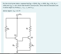
Transcribed Image Text:For the circuit given below, suppose that RB = 230k2, RE1 = 4002, RE2 = 02, Rc =
1002 and Vcc = +6V. Given that the BJT's have B=100, verify that the transistors are
in active region by finding icı, VCE1, İc2 and VCE2.
Active region: VBe = 0.7V
Q+Vc
RB
Rc
Q1
Q2
Re1
RE2
Expert Solution
This question has been solved!
Explore an expertly crafted, step-by-step solution for a thorough understanding of key concepts.
Step by stepSolved in 2 steps with 2 images

Knowledge Booster
Learn more about
Need a deep-dive on the concept behind this application? Look no further. Learn more about this topic, electrical-engineering and related others by exploring similar questions and additional content below.Similar questions
- Just need 1d and 1e answered.arrow_forwardMost of the following statements about integrated circuits arecorrect, but one is not. Which statement is NOT true? Select one: a. Transistors are constructed in a small area of an integrated circuit,and are connected to other transistors by wires that are embedded inthe integrated circuit b. Wires that carry signals may be embedded in a substrate without a shortcircuit because a short circuit would require a signal to cross areverse biased junction c. Each transistor on an integrated circuit is manufactured individually,one at a time d. An integrated circuit contains several layersarrow_forwardGiven shows the mutual characteristic for a junction gate field effect transistor. When the gate-source voltage is -2.5V, determine the value of drain current, the dynamic value of forward transconductance. -2.5V 2.5V - 12mA 5 mA -5.0-4.5 -4.0 -3.5 -3.0-2.5 -2.0 -1.5 -1.0 -0.5 Gate-source voltage, VGs (V) 0 20 18 16 14 12 10 00 6 4 2 0 Drain current, (mA)arrow_forward
- A pnp transistor has VEB=0.7V at a collector current of 1mA. What do you expect VEB to become at Ic=10mA? At Ic=100mA?arrow_forwardSketch all applicable depletion regions for a p-channel MOSFET when the source remains grounded, an appropriate voltage is applied to the gate to induce a channel, and a drain voltage is applied that causes a reverse bias between the drain and the substrate.arrow_forwardP.arrow_forward
- A (conventional) current of 26 uA flows out of the base of a certain transistor. The emitter current is 0.94 mA. What is the collector current and what kind of transistor is it (npn or pnp)? Draw a transistor symbol and label all current flows, showing directions and magnitudes.arrow_forwardA certain npn silicon transistor has vBE=0.7 V for iB=0.1 mA at a temperature of 30°C. Sketch the input characteristic to scale at 30°C. What is the approximate value of vBE for iB = 0.1 mA at 180°C? (Use the rule of thumb that vBE is reduced in magnitude by 2 mV per degree increase in temperature.) Sketch the input characteristic to scale at 180°C.arrow_forwardA silicon transistor is biased with base resistor method. If B=100, VBE =0.7 V, zero signal collector current IC = 1 mA and VCC = 6V , what is the %3D value of the base resistor RB? Select one: a. 530 kQ b. 105 kQ c. 315 k. d. None of the abovearrow_forward
- The maximum drain current for the n-channel enrichment type MOSFET is 30 mA.Determine VGS with this current level if k= 0.06x10⁻³ A/V2 and VT is the maximum value.arrow_forwardConsider the circuit in figure 1. Determine the base, collector, and emitter voltages and currents, as well as the currents through R1 and R2. Assume that the transistor is ideal, and that its β = 10. Further, determine for what values of R1 and R2 is the transistor in its three regions (Cutoff, Saturation, and Active). Finally, replace the transistor with a PNP transistor, how does this change the results?arrow_forwardConsider the BJT transistor circuit in Figure 1. If DC = 150 and VBE = 0.65V, calculate:Base (IB), collector (IC), emitter (IE) currents, voltages VB, VC, VE, VCE and VCB. And what is PD(max) at 75OC? If the power dissipation derating factor for the transistor is 2mW/oC and the PD(max) is0.5 W at 25OCarrow_forward
arrow_back_ios
SEE MORE QUESTIONS
arrow_forward_ios
Recommended textbooks for you
 Introductory Circuit Analysis (13th Edition)Electrical EngineeringISBN:9780133923605Author:Robert L. BoylestadPublisher:PEARSON
 Delmar's Standard Textbook Of ElectricityElectrical EngineeringISBN:9781337900348Author:Stephen L. HermanPublisher:Cengage Learning
 Programmable Logic ControllersElectrical EngineeringISBN:9780073373843Author:Frank D. PetruzellaPublisher:McGraw-Hill Education
 Fundamentals of Electric CircuitsElectrical EngineeringISBN:9780078028229Author:Charles K Alexander, Matthew SadikuPublisher:McGraw-Hill Education
 Electric Circuits. (11th Edition)Electrical EngineeringISBN:9780134746968Author:James W. Nilsson, Susan RiedelPublisher:PEARSON
 Engineering ElectromagneticsElectrical EngineeringISBN:9780078028151Author:Hayt, William H. (william Hart), Jr, BUCK, John A.Publisher:Mcgraw-hill Education,

Introductory Circuit Analysis (13th Edition)
Electrical Engineering
ISBN:9780133923605
Author:Robert L. Boylestad
Publisher:PEARSON

Delmar's Standard Textbook Of Electricity
Electrical Engineering
ISBN:9781337900348
Author:Stephen L. Herman
Publisher:Cengage Learning

Programmable Logic Controllers
Electrical Engineering
ISBN:9780073373843
Author:Frank D. Petruzella
Publisher:McGraw-Hill Education

Fundamentals of Electric Circuits
Electrical Engineering
ISBN:9780078028229
Author:Charles K Alexander, Matthew Sadiku
Publisher:McGraw-Hill Education

Electric Circuits. (11th Edition)
Electrical Engineering
ISBN:9780134746968
Author:James W. Nilsson, Susan Riedel
Publisher:PEARSON

Engineering Electromagnetics
Electrical Engineering
ISBN:9780078028151
Author:Hayt, William H. (william Hart), Jr, BUCK, John A.
Publisher:Mcgraw-hill Education,