
Introductory Circuit Analysis (13th Edition)
13th Edition
ISBN: 9780133923605
Author: Robert L. Boylestad
Publisher: PEARSON
expand_more
expand_more
format_list_bulleted
Related questions
Question
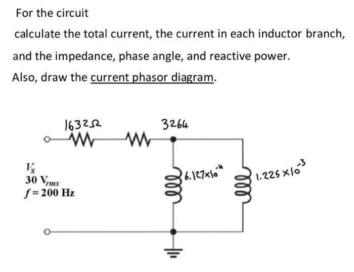

Transcribed Image Text:For the circuit
calculate the total current, the current in each inductor branch,
and the impedance, phase angle, and reactive power.
Also, draw the current phasor diagram.
163252
www
Vs
30 Vrms
f = 200 Hz
www
3264
36.127x10⁴
мее
ell
-3
1.225x10
Expert Solution
This question has been solved!
Explore an expertly crafted, step-by-step solution for a thorough understanding of key concepts.

Step by stepSolved in 7 steps with 14 images

Knowledge Booster


Learn more about
Need a deep-dive on the concept behind this application? Look no further. Learn more about this topic, electrical-engineering and related others by exploring similar questions and additional content below.Similar questions
- The IT servers for a medium-sized company need to be protected fromgrid failures (e.g. blackout) and thus is powered through anuninterruptable power supply (UPS) unit. The UPS consists of a 3-phase diode rectifier powering the dc bus, which then splits between a3-phase inverter unit and a battery energy storage system (BESS). UPSparameters are given in Table B2 and a general schematic is shown inFigure B2.a) Assuming that the inverter and BESS pull a combined constant current,IDC, from the dc bus, draw the approximate waveforms over one full accycle for: (i) the three ac line voltages, (ii) the three ac currents, and(iii) the total dc bus voltage.arrow_forwardA 15µF capacitor and a 470 ohm resistor are connected in series with a function generator. The supply voltage is 50V RMS 40Hz. Find the reactive power for this circuit.arrow_forward1) Two identical voltage waveforms of difference phase angles are shown in Figure B. Write down the expression of waveforms A and B clearly. HUS Voltage (V) 8 0 K/N B 7: ST otarrow_forward
arrow_back_ios
arrow_forward_ios
Recommended textbooks for you
- Introductory Circuit Analysis (13th Edition)Electrical EngineeringISBN:9780133923605Author:Robert L. BoylestadPublisher:PEARSON
 Delmar's Standard Textbook Of ElectricityElectrical EngineeringISBN:9781337900348Author:Stephen L. HermanPublisher:Cengage Learning
 Programmable Logic ControllersElectrical EngineeringISBN:9780073373843Author:Frank D. PetruzellaPublisher:McGraw-Hill Education
  Fundamentals of Electric CircuitsElectrical EngineeringISBN:9780078028229Author:Charles K Alexander, Matthew SadikuPublisher:McGraw-Hill Education
 Electric Circuits. (11th Edition)Electrical EngineeringISBN:9780134746968Author:James W. Nilsson, Susan RiedelPublisher:PEARSON
 Engineering ElectromagneticsElectrical EngineeringISBN:9780078028151Author:Hayt, William H. (william Hart), Jr, BUCK, John A.Publisher:Mcgraw-hill Education,
Introductory Circuit Analysis (13th Edition)
Electrical Engineering
ISBN:9780133923605
Author:Robert L. Boylestad
Publisher:PEARSON
Delmar's Standard Textbook Of Electricity
Electrical Engineering
ISBN:9781337900348
Author:Stephen L. Herman
Publisher:Cengage Learning
Programmable Logic Controllers
Electrical Engineering
ISBN:9780073373843
Author:Frank D. Petruzella
Publisher:McGraw-Hill Education
Fundamentals of Electric Circuits
Electrical Engineering
ISBN:9780078028229
Author:Charles K Alexander, Matthew Sadiku
Publisher:McGraw-Hill Education
Electric Circuits. (11th Edition)
Electrical Engineering
ISBN:9780134746968
Author:James W. Nilsson, Susan Riedel
Publisher:PEARSON
Engineering Electromagnetics
Electrical Engineering
ISBN:9780078028151
Author:Hayt, William H. (william Hart), Jr, BUCK, John A.
Publisher:Mcgraw-hill Education,