
Introductory Circuit Analysis (13th Edition)
13th Edition
ISBN: 9780133923605
Author: Robert L. Boylestad
Publisher: PEARSON
expand_more
expand_more
format_list_bulleted
Related questions
Question
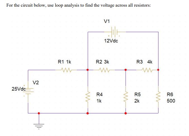

Transcribed Image Text:**Title: Analyzing Circuit Voltages Using Loop Analysis**
**Introduction**
In this educational module, we'll explore how to determine the voltage across resistors in a given circuit using loop analysis. The circuit features two voltage sources and a series of interconnected resistors.
**Circuit Description**
The circuit consists of the following elements:
- **Voltage Sources**:
- V1: 12 Vdc
- V2: 25 Vdc
- **Resistors**:
- R1: 1 kΩ
- R2: 3 kΩ
- R3: 4 kΩ
- R4: 1 kΩ
- R5: 2 kΩ
- R6: 500 Ω
**Circuit Layout**
- V1 (12 Vdc) is connected in series with three resistors: R1 (1 kΩ), R2 (3 kΩ), and R3 (4 kΩ).
- V2 (25 Vdc) is connected to R1 and branches off into another path through R4 (1 kΩ) and R5 (2 kΩ) that converge back into the main loop.
- R6 (500 Ω) is connected in parallel to the above branch.
**Objective**
Our goal is to use loop analysis (also known as mesh analysis) to calculate the voltage drop across each resistor in the circuit.
**Procedure**
1. **Identify and Define Loops**: Begin by identifying the independent loops within the circuit. Loops are closed paths that do not enclose other loops.
2. **Apply Kirchhoff’s Voltage Law (KVL)**: Write the KVL equation for each loop. According to KVL, the sum of the voltages around any closed loop in a circuit must equal zero.
3. **Formulate Equations**: Solve the system of equations derived from KVL to find the current through each loop.
4. **Calculate Voltage Drops**: Use the current values to compute the voltage drop across each resistor using Ohm's Law (V = IR).
**Conclusion**
Analyzing complex circuits using loop analysis provides valuable insight into the behavior of electrical components and systems. This method allows for the effective calculation of voltage and current in multiple-loop circuits, facilitating deeper understanding and design optimization in electronic applications.
Expert Solution
This question has been solved!
Explore an expertly crafted, step-by-step solution for a thorough understanding of key concepts.

This is a popular solution

Trending nowThis is a popular solution!

Step by stepSolved in 2 steps with 2 images

Knowledge Booster


Learn more about
Need a deep-dive on the concept behind this application? Look no further. Learn more about this topic, electrical-engineering and related others by exploring similar questions and additional content below.Similar questions
arrow_back_ios
arrow_forward_ios
Recommended textbooks for you
- Introductory Circuit Analysis (13th Edition)Electrical EngineeringISBN:9780133923605Author:Robert L. BoylestadPublisher:PEARSON
 Delmar's Standard Textbook Of ElectricityElectrical EngineeringISBN:9781337900348Author:Stephen L. HermanPublisher:Cengage Learning
 Programmable Logic ControllersElectrical EngineeringISBN:9780073373843Author:Frank D. PetruzellaPublisher:McGraw-Hill Education
  Fundamentals of Electric CircuitsElectrical EngineeringISBN:9780078028229Author:Charles K Alexander, Matthew SadikuPublisher:McGraw-Hill Education
 Electric Circuits. (11th Edition)Electrical EngineeringISBN:9780134746968Author:James W. Nilsson, Susan RiedelPublisher:PEARSON
 Engineering ElectromagneticsElectrical EngineeringISBN:9780078028151Author:Hayt, William H. (william Hart), Jr, BUCK, John A.Publisher:Mcgraw-hill Education,
Introductory Circuit Analysis (13th Edition)
Electrical Engineering
ISBN:9780133923605
Author:Robert L. Boylestad
Publisher:PEARSON
Delmar's Standard Textbook Of Electricity
Electrical Engineering
ISBN:9781337900348
Author:Stephen L. Herman
Publisher:Cengage Learning
Programmable Logic Controllers
Electrical Engineering
ISBN:9780073373843
Author:Frank D. Petruzella
Publisher:McGraw-Hill Education
Fundamentals of Electric Circuits
Electrical Engineering
ISBN:9780078028229
Author:Charles K Alexander, Matthew Sadiku
Publisher:McGraw-Hill Education
Electric Circuits. (11th Edition)
Electrical Engineering
ISBN:9780134746968
Author:James W. Nilsson, Susan Riedel
Publisher:PEARSON
Engineering Electromagnetics
Electrical Engineering
ISBN:9780078028151
Author:Hayt, William H. (william Hart), Jr, BUCK, John A.
Publisher:Mcgraw-hill Education,