Structural Analysis
6th Edition
ISBN: 9781337630931
Author: KASSIMALI, Aslam.
Publisher: Cengage,
expand_more
expand_more
format_list_bulleted
Concept explainers
Question

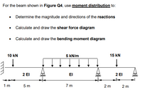
Transcribed Image Text:For the beam shown in Figure Q4, use moment distribution to:
• Determine the magnitude and directions of the reactions
• Calculate and draw the shear force diagram
• Calculate and draw the bending moment diagram
10 kN
5 kN/m
15 kN
2 El
2 El
EI
1 m
5 m
7 m
2 m
2 m

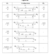
Transcribed Image Text:MA
Configuration
MB
PL
MA
M.
PL
8.
8.
L/2
L/2
wL
MA
M.
wL
12
В
12
L
P
Pab
MA
M.
Pa'b
B
L
a
b
L
P
3PL
MA
16
L/2
L/2
MA
L
MA
Pab(2L-a)
a
b
Expert Solution
This question has been solved!
Explore an expertly crafted, step-by-step solution for a thorough understanding of key concepts.
Step by stepSolved in 2 steps with 7 images

Knowledge Booster
Learn more about
Need a deep-dive on the concept behind this application? Look no further. Learn more about this topic, civil-engineering and related others by exploring similar questions and additional content below.Similar questions
- Question 4(a) The uniform bar shown in Figure 4 weighs 428 N. It is supported by a pin at A and a cable that runs around the pulley, D. It is subjected to a uniformly distributed load of 17.7 N/m and 12.5 Nm clockwise moment at E. Beam is in equilibrium position as shown in the Figure. Take a = 0.41 m and b = 2.5 m. Determine the tension in the cable and the reaction force at A, both in Newtons. w N/m 75° A ▼▼ ▼ ▼ 12.5 Nm B E 1 m 0.5 m m b Figure 4 Question 4(b) Find a truss from your neighborhood where you can take a photo safely. It does not have to be taken from the perfect angle and as long as we can see the complete truss that is good enough. One photo would be ideal but upto 3 photos can be used. Include these photos in your solutions for this question and based on these photos draw this 2D truss (exact dimensions are not required) with the supports too. Comment on the possible loads and their locations that may be applied to the truss. Discuss the assumptions that you have to…arrow_forwardFor the simply supported beam subjected to the loading shown, derive equations for the shear force V and the bending moment M for any location in the beam. (Place the origin at point A.) Let a=1.50 m, b=5.00 m, PA = 75kN, and PC = 90kN. Construct the shear-force and bending-moment diagrams. Calculate the reaction forces By and Dy acting on the beam. Positive values for the reactions are indicated by the directions of the red arrows shown on the free-body diagram below.arrow_forwardQ6.1. For the two-dimensional truss structure shown in the figure, determine all the nodal deflections and nodal forces. The support reaction forces, Rix, Rly and R3x are also indicated on this figure next to the supports. Both bar members (1) and (2) are of length 2.0 m. Each member has a cross-sectional area of 80 mm² and a modulus of elasticity of 200 GPa, Ignore the possibility of buckling in the compression members. Ans.: u2x=0.625 mm, u2y=-2.061, u3y=-0.375 mm, Rix--5 kN, R₁-3 kN, R3x=3 kN. R R RIS (1) (3) Fig. 1 3 kN 2 kN Xarrow_forward
Recommended textbooks for you

 Structural Analysis (10th Edition)Civil EngineeringISBN:9780134610672Author:Russell C. HibbelerPublisher:PEARSON
 Principles of Foundation Engineering (MindTap Cou...Civil EngineeringISBN:9781337705028Author:Braja M. Das, Nagaratnam SivakuganPublisher:Cengage Learning
 Fundamentals of Structural AnalysisCivil EngineeringISBN:9780073398006Author:Kenneth M. Leet Emeritus, Chia-Ming Uang, Joel LanningPublisher:McGraw-Hill Education
 Traffic and Highway EngineeringCivil EngineeringISBN:9781305156241Author:Garber, Nicholas J.Publisher:Cengage Learning


Structural Analysis (10th Edition)
Civil Engineering
ISBN:9780134610672
Author:Russell C. Hibbeler
Publisher:PEARSON

Principles of Foundation Engineering (MindTap Cou...
Civil Engineering
ISBN:9781337705028
Author:Braja M. Das, Nagaratnam Sivakugan
Publisher:Cengage Learning

Fundamentals of Structural Analysis
Civil Engineering
ISBN:9780073398006
Author:Kenneth M. Leet Emeritus, Chia-Ming Uang, Joel Lanning
Publisher:McGraw-Hill Education


Traffic and Highway Engineering
Civil Engineering
ISBN:9781305156241
Author:Garber, Nicholas J.
Publisher:Cengage Learning