
Introductory Circuit Analysis (13th Edition)
13th Edition
ISBN: 9780133923605
Author: Robert L. Boylestad
Publisher: PEARSON
expand_more
expand_more
format_list_bulleted
Related questions
Concept explainers
Question

Transcribed Image Text:### Circuit Description
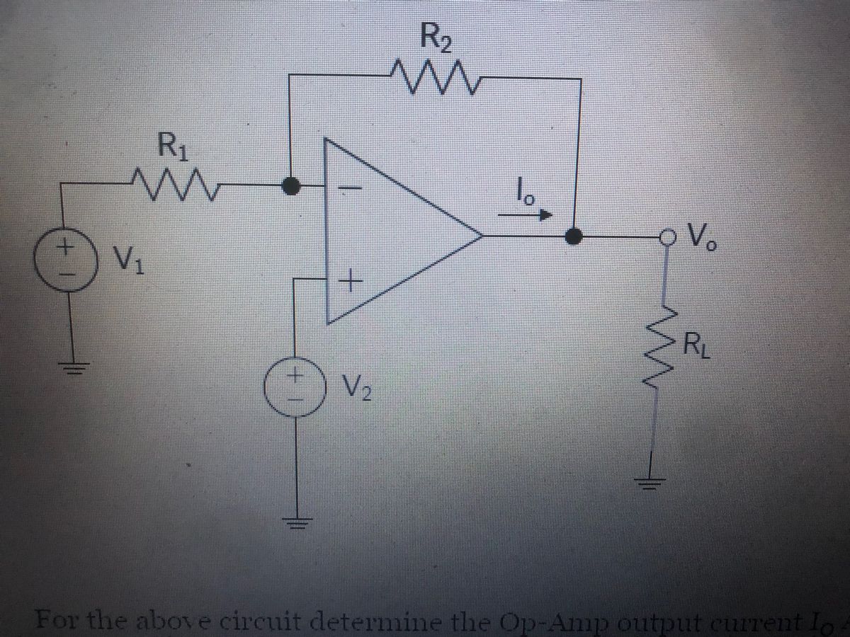
The diagram is an operational amplifier (op-amp) circuit with the following components and connections:
- **Voltage Sources:**
- \( V_1 \): Connected to the inverting input through resistor \( R_1 \).
- \( V_2 \): Connected to the non-inverting input.
- **Resistors:**
- \( R_1 \): Connects \( V_1 \) to the inverting input.
- \( R_2 \): Feedback resistor connecting the output \( V_o \) back to the inverting input.
- \( R_L \): Load resistor connected to the output \( V_o \).
- **Operational Amplifier:**
- Standard symbol for an op-amp with a non-inverting (\(+\)) and an inverting (\(-\)) input.
- The output voltage is labeled as \( V_o \).
- The current flowing out of the op-amp is \( I_o \).
### Objective
The task associated with the circuit is to determine the op-amp's output current \( I_o \).
This configuration is typical in linear amplifier applications, where the relationship between inputs \( V_1\), \( V_2\), and output \( V_o\) can be analyzed using principles of superposition and op-amp characteristics (ideal conditions: infinite open-loop gain, infinite input impedance, zero output impedance).

Transcribed Image Text:For the above circuit, determine the Op-Amp output current \( I_o \) in Amps (Note: This is not the current through the load resistor). Round your answer to the nearest single-digit decimal place. Do not enter units. For example, if you calculate 32.58 Amps, then enter 32.6 as your submitted answer. You may assume the ideal op-amp and that it is operating in the linear region.
- \( V_1 = 8 \) Volts
- \( V_2 = 9 \) Volts
- \( R_1 = 8 \) Ohms
- \( R_2 = 2 \) Ohms
- \( R_L = 7 \) Ohms
Expert Solution
This question has been solved!
Explore an expertly crafted, step-by-step solution for a thorough understanding of key concepts.

This is a popular solution

Trending nowThis is a popular solution!

Step by stepSolved in 2 steps with 2 images

Knowledge Booster


Learn more about
Need a deep-dive on the concept behind this application? Look no further. Learn more about this topic, electrical-engineering and related others by exploring similar questions and additional content below.Recommended textbooks for you
- Introductory Circuit Analysis (13th Edition)Electrical EngineeringISBN:9780133923605Author:Robert L. BoylestadPublisher:PEARSON
 Delmar's Standard Textbook Of ElectricityElectrical EngineeringISBN:9781337900348Author:Stephen L. HermanPublisher:Cengage Learning
 Programmable Logic ControllersElectrical EngineeringISBN:9780073373843Author:Frank D. PetruzellaPublisher:McGraw-Hill Education
  Fundamentals of Electric CircuitsElectrical EngineeringISBN:9780078028229Author:Charles K Alexander, Matthew SadikuPublisher:McGraw-Hill Education
 Electric Circuits. (11th Edition)Electrical EngineeringISBN:9780134746968Author:James W. Nilsson, Susan RiedelPublisher:PEARSON
 Engineering ElectromagneticsElectrical EngineeringISBN:9780078028151Author:Hayt, William H. (william Hart), Jr, BUCK, John A.Publisher:Mcgraw-hill Education,
Introductory Circuit Analysis (13th Edition)
Electrical Engineering
ISBN:9780133923605
Author:Robert L. Boylestad
Publisher:PEARSON
Delmar's Standard Textbook Of Electricity
Electrical Engineering
ISBN:9781337900348
Author:Stephen L. Herman
Publisher:Cengage Learning
Programmable Logic Controllers
Electrical Engineering
ISBN:9780073373843
Author:Frank D. Petruzella
Publisher:McGraw-Hill Education
Fundamentals of Electric Circuits
Electrical Engineering
ISBN:9780078028229
Author:Charles K Alexander, Matthew Sadiku
Publisher:McGraw-Hill Education
Electric Circuits. (11th Edition)
Electrical Engineering
ISBN:9780134746968
Author:James W. Nilsson, Susan Riedel
Publisher:PEARSON
Engineering Electromagnetics
Electrical Engineering
ISBN:9780078028151
Author:Hayt, William H. (william Hart), Jr, BUCK, John A.
Publisher:Mcgraw-hill Education,