
Introductory Circuit Analysis (13th Edition)
13th Edition
ISBN: 9780133923605
Author: Robert L. Boylestad
Publisher: PEARSON
expand_more
expand_more
format_list_bulleted
Related questions
Question
find voltage through R1, R2, R3,R4, and R5.
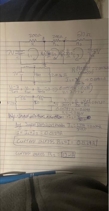

Transcribed Image Text:V
V₂
7V7
200
+
2001
M
200
Ni
5/0
R.
(1) 83 56 12 (1230012)
3560
2005
w
mo
330
51052
5200.36.52
11=Y₁ -009420
18036
+ V/²=0 0-009384 = 0.035
455-36
V=3.77U
R Plox - 200300
(stor330)
V₁V₁ts=147,37
#
V.
5V 347-57 330 510
0.00787 v.--0-0018
V₁=-12460
My Speedom - 1₂ = 4/₁
by Super position therer 1₂=1.246
I = 1₁ + 1₂ = 0.0129A
Current across R₂=1= 0.0129A/
current across R₂ = 13 MA
0.003994
Expert Solution
This question has been solved!
Explore an expertly crafted, step-by-step solution for a thorough understanding of key concepts.

Step by stepSolved in 2 steps with 2 images

Knowledge Booster

Similar questions
- R1 Vs R2 R4 Vo R3 For the circuit given in the figure, Vs=12V, R1 = 12 Ohm, R2= 8 Ohm, R3=10 Ohm R4=6 Ohm. For this circuit, find the Thévenin resistance (RThévenin). Notes: 1-Use a calculator and try to be very precise. 2-Approximations may lead you to a result that is very off from the answer. 3-Use dot as the decimal separator. 4-DO NOT WRITE OHM IN THE ANSWER. If your answer is 7.89 Ohm Write 7.89 only.arrow_forwardConsider a circuit that contains two switches as shown in Figure Q4. The switch on the right-hand side can be connected to nodes S₁ or S₂. The two switches operate as follows: ➤ If this right-hand switch is connected to node S₁, the switch labelled S3 is in the open position. If the right-hand switch is connected to node S₂, the switch labelled S3 is in the closed position. Both switches switch instantaneously and simultaneously. R = 20 ΚΩ C = 0.25 nF HE +21 S3 L=1 mH R, = 20 ΚΩ S₁ 1S₂ AS = SA iL Figure Q4 a) After being connected to node S₂ for a very long time, the right-hand switch is connected to node S₁ at t = 0. Derive a differential equation for the current through the inductor iz(t) and find an expression for iz(t) for all times > 0. Use numerical values for all known circuit elements ONLY in the final expression of iz(t) b) Following the events outlined in part a), the right-hand switch is connected to node S₂ at t = 5 µs. Derive a differential equation for the current through…arrow_forwardAfter the jumper wire is connected across D1 in step 4, what is the new potential of the low side of D1, relative to ground ?arrow_forward
- Resistor and RC Circuits Problem 12: Consider the circuit in the figure, with the current directions defined as shown. There are four resistors in this circuit (R1, R2, R3, and R4) and four batteries with emfs ℰ1 = 15.5 V, ℰ2 = 3.5 V, ℰ3 = 14 V, and ℰ4 = 27.3 V, each with internal resistance given by ri as marked in the figure. Part (a) Calculate the current I1 in amps. Part (b) Calculate the current I2 in amps. Part (c) Calculate the current I3 in amps.arrow_forwardUse the Principle of Superposition to determine the current i through R3 in the Figure. Let R1 = 100, R2 = 40, R3 = 20, R4 = 20, R5= 20, Vs 10 V, Is = 2A. ww VS R3 ww wwwarrow_forwardConsider the following resistor network: i₁ = E A, 1₂ = Voltage gain across I is b. Report the voltage gain across the current source I. (Click on the image to enlarge) Suppose R₁ = 60, R₂ = 50, R3 = 142, R₁ = 4, R5 = 4N, E = 28V and I = 6A. Set up and solve a linear system for the loop currents and the voltage across the current source as shown in the online notes. a. Report the loop currents i1, 12 and i3 (positive for clockwise direction). V R₁ A, 23 = R₂. R3 R4 A R5arrow_forward
- 8arrow_forwardPlease see attached screen shot for questions a-f.arrow_forwardShown in the figure below is an electrical circuit containing three resistors and two batteries. R3 10 R2 R1 Write down the Kirchhoff Junction equation and solve it for I, in terms of I, and Iz. Write the result here: Write down the Kirchhoff Loop equation for a loop that starts at the lower left corner and follows the perimeter of the circuit diagram clockwise. Write down the Kirchhoff Loop equation for a loop that starts at the lower left corner and touches the components R1, R2, and 4V. The resistors in the circuit have the following values: R, = 130 • R2 = 50 R3 = 10 Solve for all the following (some answers may be negative): | Amperes I = I, = Amperes Iz = Amperes NOTE: For the equations, put in resistances and currents SYMBOLICALLY using variables like RR2,R3 and I,,12,13. Use numerical values of 10 and 4 for the voltages.arrow_forward
arrow_back_ios
arrow_forward_ios
Recommended textbooks for you
- Introductory Circuit Analysis (13th Edition)Electrical EngineeringISBN:9780133923605Author:Robert L. BoylestadPublisher:PEARSON
 Delmar's Standard Textbook Of ElectricityElectrical EngineeringISBN:9781337900348Author:Stephen L. HermanPublisher:Cengage Learning
 Programmable Logic ControllersElectrical EngineeringISBN:9780073373843Author:Frank D. PetruzellaPublisher:McGraw-Hill Education
  Fundamentals of Electric CircuitsElectrical EngineeringISBN:9780078028229Author:Charles K Alexander, Matthew SadikuPublisher:McGraw-Hill Education
 Electric Circuits. (11th Edition)Electrical EngineeringISBN:9780134746968Author:James W. Nilsson, Susan RiedelPublisher:PEARSON
 Engineering ElectromagneticsElectrical EngineeringISBN:9780078028151Author:Hayt, William H. (william Hart), Jr, BUCK, John A.Publisher:Mcgraw-hill Education,
Introductory Circuit Analysis (13th Edition)
Electrical Engineering
ISBN:9780133923605
Author:Robert L. Boylestad
Publisher:PEARSON
Delmar's Standard Textbook Of Electricity
Electrical Engineering
ISBN:9781337900348
Author:Stephen L. Herman
Publisher:Cengage Learning
Programmable Logic Controllers
Electrical Engineering
ISBN:9780073373843
Author:Frank D. Petruzella
Publisher:McGraw-Hill Education
Fundamentals of Electric Circuits
Electrical Engineering
ISBN:9780078028229
Author:Charles K Alexander, Matthew Sadiku
Publisher:McGraw-Hill Education
Electric Circuits. (11th Edition)
Electrical Engineering
ISBN:9780134746968
Author:James W. Nilsson, Susan Riedel
Publisher:PEARSON
Engineering Electromagnetics
Electrical Engineering
ISBN:9780078028151
Author:Hayt, William H. (william Hart), Jr, BUCK, John A.
Publisher:Mcgraw-hill Education,