Introductory Circuit Analysis (13th Edition)
13th Edition
ISBN: 9780133923605
Author: Robert L. Boylestad
Publisher: PEARSON
expand_more
expand_more
format_list_bulleted
Question
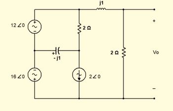
Find Vo for the circuit in Figure using Nodal Analysis
Show your complete solution

Transcribed Image Text:12 20
16 20
1 2 +}
+21
+ 21)
#t
-j1
३
20
+
j1
240
20
Vo
Expert Solution
This question has been solved!
Explore an expertly crafted, step-by-step solution for a thorough understanding of key concepts.
Step by stepSolved in 3 steps with 2 images

Knowledge Booster
Learn more about
Need a deep-dive on the concept behind this application? Look no further. Learn more about this topic, electrical-engineering and related others by exploring similar questions and additional content below.Similar questions
- HW10: R1 Vs Solve for the output voltage in the op-amp circuit to the right. R + R2 Vo Rarrow_forwardFind r_total and i_total for the given circuit belowarrow_forwardQ-4: By using mathimatical approach, find Ipo. Vosq and Vsp for the circuit of the figure shown, where Ipss = 8mA and Vp = - 8V I8V 2.2K2 0.39K -4Varrow_forward
- Can you please help with the problem in the image?arrow_forwardThis circuit will shift and scale the Vin range of -12V to +12V into the ADC range of OV to 5V. Find R1 if R2=12k, R3=12k, R4=2.5k. +5Vref R4 Vin R3 +5Vref ADC R1 R2 +arrow_forwardPlease, I need the correct solution. I need to design a Full Adder circuit using a Comparator, and this is the solution, but I'm not sure if it's correct or not. Can you draw the circuit?arrow_forward
- Work out vbout and vcoutarrow_forwardThe data input waveform and data select waveforms in Figure 6-38 are applied to a 40. demultiplexer with eight active-HIGH outputs. Show each output waveform in relation to the given waveforms. So Select S1 inputs S2 Data input FIGURE 6-38 1 DOOmence of BCD codes appliedarrow_forwardPlease solve max in 15-20 minutes and no reject. The option answer can u see in imagearrow_forward
- A series RL circuit contains two resistors and two inductors.The resistors are 33ohms and 47ohms.The inductors have inductive reactance of 60ohms and 30ohms. When calculating the circuit value, the total resistance used is?arrow_forwarddefine a series circuitarrow_forwarddesign a weighted summer that provides an output voltage vo=v1+v2+2v3+5v4-v5 the maximum resistance is to be limited to 1 ohmarrow_forward
arrow_back_ios
arrow_forward_ios
Recommended textbooks for you
 Introductory Circuit Analysis (13th Edition)Electrical EngineeringISBN:9780133923605Author:Robert L. BoylestadPublisher:PEARSON
 Delmar's Standard Textbook Of ElectricityElectrical EngineeringISBN:9781337900348Author:Stephen L. HermanPublisher:Cengage Learning
 Programmable Logic ControllersElectrical EngineeringISBN:9780073373843Author:Frank D. PetruzellaPublisher:McGraw-Hill Education
 Fundamentals of Electric CircuitsElectrical EngineeringISBN:9780078028229Author:Charles K Alexander, Matthew SadikuPublisher:McGraw-Hill Education
 Electric Circuits. (11th Edition)Electrical EngineeringISBN:9780134746968Author:James W. Nilsson, Susan RiedelPublisher:PEARSON
 Engineering ElectromagneticsElectrical EngineeringISBN:9780078028151Author:Hayt, William H. (william Hart), Jr, BUCK, John A.Publisher:Mcgraw-hill Education,

Introductory Circuit Analysis (13th Edition)
Electrical Engineering
ISBN:9780133923605
Author:Robert L. Boylestad
Publisher:PEARSON

Delmar's Standard Textbook Of Electricity
Electrical Engineering
ISBN:9781337900348
Author:Stephen L. Herman
Publisher:Cengage Learning

Programmable Logic Controllers
Electrical Engineering
ISBN:9780073373843
Author:Frank D. Petruzella
Publisher:McGraw-Hill Education

Fundamentals of Electric Circuits
Electrical Engineering
ISBN:9780078028229
Author:Charles K Alexander, Matthew Sadiku
Publisher:McGraw-Hill Education

Electric Circuits. (11th Edition)
Electrical Engineering
ISBN:9780134746968
Author:James W. Nilsson, Susan Riedel
Publisher:PEARSON

Engineering Electromagnetics
Electrical Engineering
ISBN:9780078028151
Author:Hayt, William H. (william Hart), Jr, BUCK, John A.
Publisher:Mcgraw-hill Education,