
Introductory Circuit Analysis (13th Edition)
13th Edition
ISBN: 9780133923605
Author: Robert L. Boylestad
Publisher: PEARSON
expand_more
expand_more
format_list_bulleted
Related questions
Concept explainers
Question
Find V, and V2 in the circuit in Fig. P3.6 using nodal analysis.

Transcribed Image Text:**Nodal Analysis: Finding \( V_1 \) and \( V_2 \) in a Circuit**
**Problem Statement:**
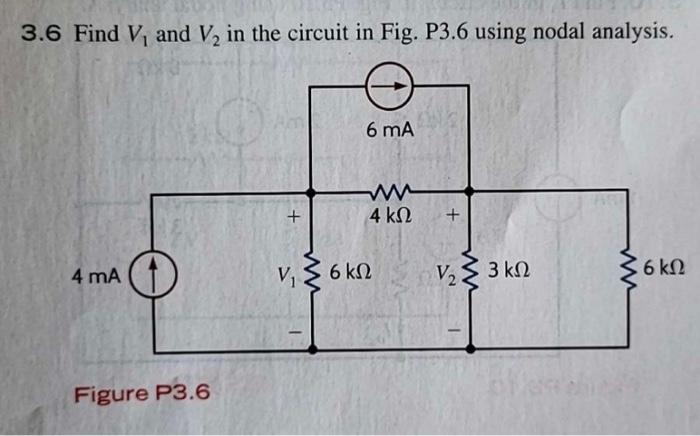
3.6 Find \( V_1 \) and \( V_2 \) in the circuit in Fig. P3.6 using nodal analysis.
**Figure P3.6 Description:**
The circuit diagram in Figure P3.6 consists of multiple components:
- A current source of 4 mA (milliamperes) is connected to a node.
- At this node, a 6 kΩ (kilohms) resistor is connected to the ground, with the voltage at this node denoted as \( V_1 \).
- Moving towards the right, there is a 4 kΩ resistor connected in series between two nodes.
- The second node, where the voltage is denoted as \( V_2 \), has a 3 kΩ resistor connected in parallel to a current source of 6 mA.
- Additionally, there is a 6 kΩ resistor connected to another node at the extreme right from \( V_2 \), going to the ground.
**Diagram Description:**
1. **Left Node:** Connected to the 4 mA current source and a 6 kΩ resistor to the ground, marked as \( V_1 \).
2. **Middle Node (between Resistors):** Connected via a 4 kΩ resistor from the left node, and has a parallel connection with the 6 mA current source and a 3 kΩ resistor, and another connection to \( V_2 \).
3. **Right Node:** Connected to the 6 kΩ resistor grounded, marked as \( V_2 \).
The goal of the problem is to use nodal analysis to determine the voltages \( V_1 \) and \( V_2 \) at these nodes.
**Steps for Nodal Analysis:**
1. **Identify all Nodes and Assign Variables:**
- \( V_1 \) at the leftmost node.
- \( V_2 \) at the middle node between \( 4 \text{ kΩ} \) and \( 3 \text{ kΩ} \) resistors.
2. **Apply KCL (Kirchhoff's Current Law) at each node:**
- For \( V_1 \): Sum of currents leaving \( V_1 \) = Sum of currents entering \( V_
Expert Solution
This question has been solved!
Explore an expertly crafted, step-by-step solution for a thorough understanding of key concepts.

Step by stepSolved in 3 steps with 2 images

Knowledge Booster


Learn more about
Need a deep-dive on the concept behind this application? Look no further. Learn more about this topic, electrical-engineering and related others by exploring similar questions and additional content below.Similar questions
- I need the answer as soon as possiblearrow_forwardSolution with fbdarrow_forward(iii) A team member in your design team has obtained the following relationship between signals Vd and v₂: vd = -2v, +3 (This may or may not be correct) ----- (1) An OPAMP topology that can condition signal to obtain signal is given below (Fig. 3.3). Design the topology components of Fig. 3.3 to produce signal va as output, given signal vas input based on the relationship given in equation (1). Choose R₁ = 15kN. Vs R₂= = R1=15kΩ Fig. 3.3: OPAMP topology 1 Vref = R₂ + Vref Vaarrow_forward
arrow_back_ios
arrow_forward_ios
Recommended textbooks for you
- Introductory Circuit Analysis (13th Edition)Electrical EngineeringISBN:9780133923605Author:Robert L. BoylestadPublisher:PEARSON
 Delmar's Standard Textbook Of ElectricityElectrical EngineeringISBN:9781337900348Author:Stephen L. HermanPublisher:Cengage Learning
 Programmable Logic ControllersElectrical EngineeringISBN:9780073373843Author:Frank D. PetruzellaPublisher:McGraw-Hill Education
  Fundamentals of Electric CircuitsElectrical EngineeringISBN:9780078028229Author:Charles K Alexander, Matthew SadikuPublisher:McGraw-Hill Education
 Electric Circuits. (11th Edition)Electrical EngineeringISBN:9780134746968Author:James W. Nilsson, Susan RiedelPublisher:PEARSON
 Engineering ElectromagneticsElectrical EngineeringISBN:9780078028151Author:Hayt, William H. (william Hart), Jr, BUCK, John A.Publisher:Mcgraw-hill Education,
Introductory Circuit Analysis (13th Edition)
Electrical Engineering
ISBN:9780133923605
Author:Robert L. Boylestad
Publisher:PEARSON
Delmar's Standard Textbook Of Electricity
Electrical Engineering
ISBN:9781337900348
Author:Stephen L. Herman
Publisher:Cengage Learning
Programmable Logic Controllers
Electrical Engineering
ISBN:9780073373843
Author:Frank D. Petruzella
Publisher:McGraw-Hill Education
Fundamentals of Electric Circuits
Electrical Engineering
ISBN:9780078028229
Author:Charles K Alexander, Matthew Sadiku
Publisher:McGraw-Hill Education
Electric Circuits. (11th Edition)
Electrical Engineering
ISBN:9780134746968
Author:James W. Nilsson, Susan Riedel
Publisher:PEARSON
Engineering Electromagnetics
Electrical Engineering
ISBN:9780078028151
Author:Hayt, William H. (william Hart), Jr, BUCK, John A.
Publisher:Mcgraw-hill Education,