
Introductory Circuit Analysis (13th Edition)
13th Edition
ISBN: 9780133923605
Author: Robert L. Boylestad
Publisher: PEARSON
expand_more
expand_more
format_list_bulleted
Related questions
Question

Transcribed Image Text:**Title: Calculating the Time Constant in RC Circuits**
**Introduction:**
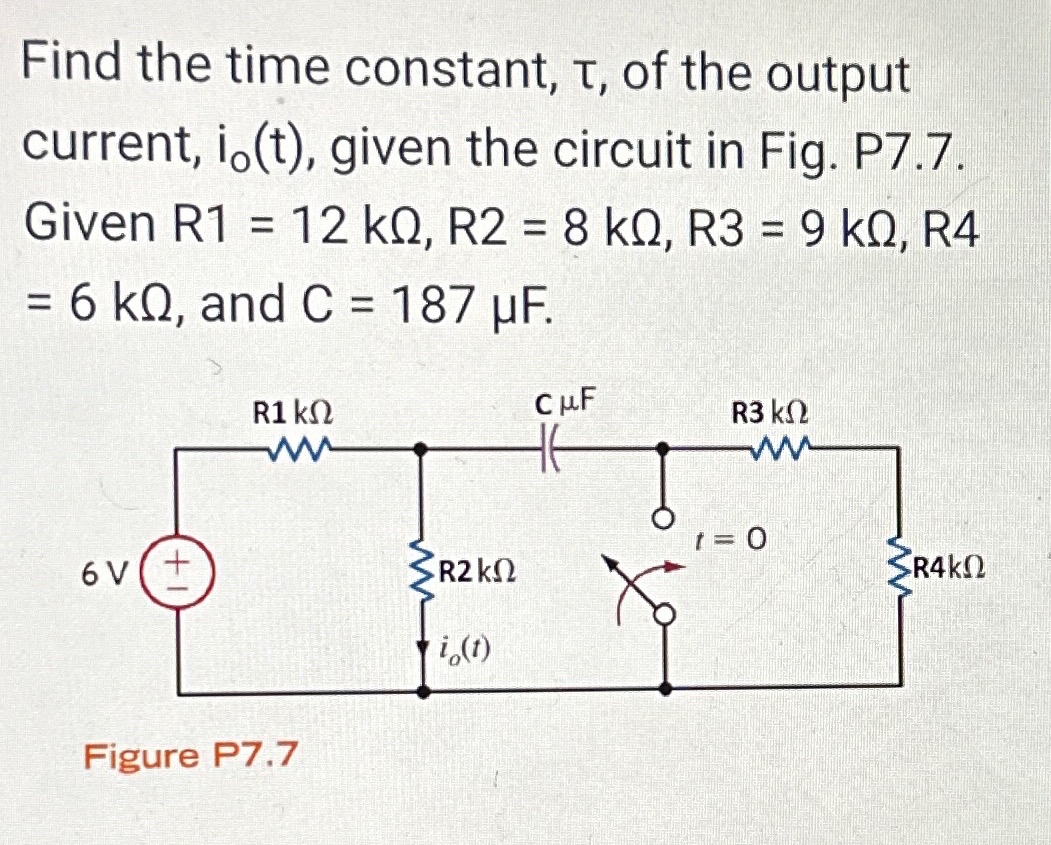
In this section, we aim to determine the time constant, \( \tau \), of the output current, \( i_o(t) \), in a given electrical circuit configuration. The circuit is depicted in Figure P7.7, and specific component values are provided for calculations.
**Circuit Description (Figure P7.7):**
The circuit consists of the following components:
- A voltage source with a potential difference of 6V.
- Four resistors with the following values:
- \( R1 = 12 \, \text{k}\Omega \)
- \( R2 = 8 \, \text{k}\Omega \)
- \( R3 = 9 \, \text{k}\Omega \)
- \( R4 = 6 \, \text{k}\Omega \)
- A capacitor with a capacitance \( C = 187 \, \mu \text{F} \).
**Circuit Analysis:**
- The resistors \( R1 \), \( R2 \), \( R3 \), and \( R4 \) are connected in a combination that affects how the capacitor charges and discharges.
- The output current \( i_o(t) \) is influenced by the time constant \( \tau \) of the RC circuit, which is crucial for understanding transient response.
- The switch in the circuit is initially open and closes at \( t = 0 \) to initiate the circuit's transient response.
**Objective:**
Determine the time constant \( \tau \), which characterizes how quickly the circuit responds to the switching event, primarily influenced by \( R \) and \( C \) values.
**Conclusion:**
The time constant \( \tau = R_{\text{eq}} \cdot C \), where \( R_{\text{eq}} \) is the equivalent resistance affecting the capacitor. Identifying \( R_{\text{eq}} \) requires combining resistances based on the configuration and simplified using series-parallel resistance calculations.
Understanding these parameters assists in predicting the circuit's behavior over time, a critical aspect of electronic design and analysis.
Expert Solution
This question has been solved!
Explore an expertly crafted, step-by-step solution for a thorough understanding of key concepts.

Step by stepSolved in 3 steps with 2 images

Knowledge Booster

Similar questions
- Solve using a differential equation. No Thevenin.arrow_forward4. For the system shown in Figure P7.3, what steady- state error can be expected for the following test inputs: 15u(t), 15tu(1), 15u(t). [Section: 7.2] R(s) S+3 3 45 FIGURE P7.3arrow_forwardPart b of the problem is shown in separate picturearrow_forward
- Using the step-by-step method, find the value of the output current, io(t), just before the switch closes (at t=0-) for the network in Fig. P7.81. Given lç, 11 mA, R1 = 3 kQ, R2 = 6 kQ, R3 = 6 k0, and R4 = 7 KQ. 1 Is mA R1 ΚΩ Figure P7.81 R3 ΚΩ R2K t = 0 Los i,(1) 2 mH SR4K! Notes on entering solution: • Enter your solution in milliAmps(mA) • Enter your solution to the nearest tenth of a mA . Do not include units in your answer .ex. 5mA is entered as 5.0 2iAarrow_forwardL:03)arrow_forwardto be the C(s) eady 20. Given the system of Figure P7.8, design the value of K so that for an input of 100tu(t), there will be a 0.01 error in the steady state. [Section: 7.4] R(s) 2039voli 204W anoitulo2 lortno) + - TOR KOL s(s+ 1) UT TOUSOULCE guollot edi bail 01 so 29ulev di-lo a 10s K FIGURE P7.8 C(s) J ripr 11 01 31242arrow_forward
arrow_back_ios
arrow_forward_ios
Recommended textbooks for you
- Introductory Circuit Analysis (13th Edition)Electrical EngineeringISBN:9780133923605Author:Robert L. BoylestadPublisher:PEARSON
 Delmar's Standard Textbook Of ElectricityElectrical EngineeringISBN:9781337900348Author:Stephen L. HermanPublisher:Cengage Learning
 Programmable Logic ControllersElectrical EngineeringISBN:9780073373843Author:Frank D. PetruzellaPublisher:McGraw-Hill Education
  Fundamentals of Electric CircuitsElectrical EngineeringISBN:9780078028229Author:Charles K Alexander, Matthew SadikuPublisher:McGraw-Hill Education
 Electric Circuits. (11th Edition)Electrical EngineeringISBN:9780134746968Author:James W. Nilsson, Susan RiedelPublisher:PEARSON
 Engineering ElectromagneticsElectrical EngineeringISBN:9780078028151Author:Hayt, William H. (william Hart), Jr, BUCK, John A.Publisher:Mcgraw-hill Education,
Introductory Circuit Analysis (13th Edition)
Electrical Engineering
ISBN:9780133923605
Author:Robert L. Boylestad
Publisher:PEARSON
Delmar's Standard Textbook Of Electricity
Electrical Engineering
ISBN:9781337900348
Author:Stephen L. Herman
Publisher:Cengage Learning
Programmable Logic Controllers
Electrical Engineering
ISBN:9780073373843
Author:Frank D. Petruzella
Publisher:McGraw-Hill Education
Fundamentals of Electric Circuits
Electrical Engineering
ISBN:9780078028229
Author:Charles K Alexander, Matthew Sadiku
Publisher:McGraw-Hill Education
Electric Circuits. (11th Edition)
Electrical Engineering
ISBN:9780134746968
Author:James W. Nilsson, Susan Riedel
Publisher:PEARSON
Engineering Electromagnetics
Electrical Engineering
ISBN:9780078028151
Author:Hayt, William H. (william Hart), Jr, BUCK, John A.
Publisher:Mcgraw-hill Education,