Related questions
Question
thumb_up100%
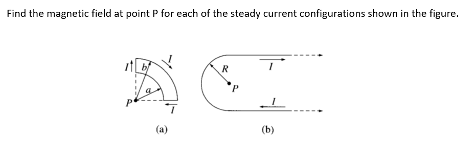

Transcribed Image Text:Find the magnetic field at point P for each of the steady current configurations shown in the figure.
R
(а)
(b)
Expert Solution
This question has been solved!
Explore an expertly crafted, step-by-step solution for a thorough understanding of key concepts.

This is a popular solution

Trending nowThis is a popular solution!

Step by stepSolved in 2 steps with 2 images

Knowledge Booster

Similar questions
- A battery is connected to wires that hand vertically (gravity acts down in the diagram). Hooks at the ends of the wires hold a horizontal copper bar (the thick bar) of mass 0.6 kg and length 0.5 meters. Another apparatus (not shown) can create a uniform magnetic field in the region of space given by the dashed rectangle. The total resistance of the circuit is 1.20 Ohms and the battery supplies 24 Volts. The magnetic field can be adjusted in strength until the bar lifts off of the hooks and levitates magnetically – not moving just above the hooks as shown. a) Determine the necessary direction of the magnetic field in the dashed rectangle. b) Calculate the required magnitude of the magnetic field.arrow_forwardA flip coil is a relatively simple device used to measure a magnetic field. It consists of a circular coil of N turns wound with fine conducting wire. The coil is attached to a ballistic galvanometer, a device that measures the total charge that passes through it. The coil is placed in a magnetic field B → such that its face is perpendicular to the field. It is then flipped through 180°, and the total charge Q that flows through the galvanometer is measured. (a) If the total resistance of the coil and galvanometer is R, what is the relationship between B and Q? Because the coil is very small, you can assume that B → is uniform over it. (b) How can you determine whether or not the magnetic field is perpendicular to the face of the coil?arrow_forwardFind the direction and magnitude of the minimum velocity of charge q = +2e that will produce the magnetic force F shown in the figure below. (Measure the angle counterclockwise from the x axis in the xz plane. Take the magnitudes of F as 1.96 x 10⁻¹¹ N and the magnitude of B as 2.19 T.) magnitude directionarrow_forward
- A proton moves in a uniform magnetic field as shown below. Find the direction of the force on the upward particle. O Up left To the right O To the left O Down O out of the page into the page right downward Barrow_forward(a) Find the magnetic field at the center of a square loop, which carries a steady current I. Let R be the distance from center to side. (b) Find the magnetic field at point P for the steady current configurations shown in the Figure below. Rarrow_forwarda loop model (loop L) for a paramagnetic material. (a) Sketch the field lines through and about the material due to the magnet.What is the direction of (b) the loop’s net magnetic dipole moment , (c) the conventional current i in the loop (clockwise or counterclockwise in the figure), and (d) the magnetic force acting on the loop?arrow_forward
- A proton moves in a circular motion perpendicular to a uniform magnetic field of 0.75 T. Find the time for the proton to make one complete circular orbit.arrow_forwardFind the direction and magnitude of the minimum velocity of charge q = +2e that will produce the magnetic force F shown in the figure below. (Measure the angle counterclockwise from the x axis in the xz plane. Take the magnitudes of F as 2.15 10-11 N and the magnitude of B as 1.83 T.) magnitude directionarrow_forwardA proton that has a speed equal to 9.00105 m/s enters a region with a uniform magnetic field that has a magnitude of 0.730T and points into the page, as shown in the figure below. The proton enters the region at an angle θ= 60°. Find the exit angle φ and the distanced d.arrow_forward
arrow_back_ios
arrow_forward_ios